Quantcast
Channel: Maintenance Guides Latest Topics
Viewing all 78 articles
Browse latest View live

How To Fix A Jumpy Speedometer

$
0
0

If you notice your speedometer is jumping around or not working at all chances are your speed sensor is wore out, or more accurately the nut that drives the sensor wont make contact with the sprocket bolt anymore.

gallery_491_4136_62525.jpg

Locate the Speed Sensor it is right over the front sprocket

gallery_491_4136_81734.jpg

Remove the 2 bolts with an 8mm nut driver

gallery_491_4136_54437.jpg

Speed sensor pulls right out

gallery_491_4136_12370.jpg

Replace the nylon nut driver the old one prys right off the shaft

gallery_491_4136_73140.jpg

Old worn out nut driver the nylon part would not make contact with the sprocket bolt.

It is a simple 5 minute fix and the replacement nut costs around 5 bucks

Part number 44080-MR7-013 speedometer, joint


VFR800, anno 2000 - does not start

$
0
0

Guys - have feeling its simple, but making it complicated. I had water in my fuel.. tank drain line clogged - I drained and clean the tank, replaced fuel filter and hoses. Bike was up and running - all good.. maybe a little uneasy on low rpm. I read about the flapper mod in this forum, so decided to give it a go and also removed the snorkel. Seem to remove the un-easiness in low rpm, so happy with this.


Next step was flushing hydraulics.. which is a task for a first timer on VFR, but its done. I had started the VFR a few times during service to make sure fuel was circulating, but one day while running idle... she coughed and stopped, and she still will not start.


1. Battery is new and fully charged

2. I hear fuel pump prime, so the flow chart I saw from Grum on relays should be ok to Fuel Pump

3. Checked for spark.. and saw spark plus got shocked, so seems electric works 🙂

4. Did check all fuses and cleaned them with contact cleaner.

5. Also noticed fuel on the plugs, not a lot but take fuel is flowing.. I am just not sure how to verify fuel flow other than drain tank (again), wrestle the fuel pump out and test externally?


Side note..

6. Working outside on the VFR but under cover - did have lot of rain and its humid tis time of year in South Florida.. suspected maybe an electric issue from moist, so jumped the service switch to check PGM-FI... this turned out to be learning experience. Found some old error codes, which i started troubleshooting (8 blink saying TP sensor, which I checked using ohm meter (OK) - pause then long blink being code 10 and BARO sensor). During the process I found out how to reset error codes in the ECM, so tried this and errors did not re-appear .. sooo putting air filter and all goodies back. Still no start.

7. As for the flapper mod, I did forget at first to plug the vacuum tube and bike has been outside, so I am sure there is some dirt on the bike, but if anything made it in there in the very short time, don't think it can prevent VFR from starting, right? Also, have a power commander, but now disconnected and wiring back to original.


Where do I go from here?.. want to learn and too stubborn to throw in the towel... yet.


Unexciting film on no start here .

Brake Pads Front

$
0
0

VFR owners delight in the ease of changing your own brake pads, 20 min job and very simple! No need to remove the calipers.

Step 1

front1.jpg

Remove the pad pin cap with flat head screwdriver

front2.jpg

Remove the pad pin with the hex key in your tool kit

front3.jpg

Of coarse this one was frozen and I stripped the key I had to get a harder key

front4.jpg

Step 2

front5.jpg

once the pad pin is out the old pads practically fall out

front6.jpg

The caliper only has pistons on one side, they are opposed by a flat plate not an opposing piston so one side might not wear like the other

To put in the new pads you must retract the pistons by pushing the caliper into the wheel first, if the brake pistons are not retracted you will not have room for the new thicker pads, there is a retaining clip at the top of the caliper where the pads sort of clip into to hold them in, slide them in the same way the old ones came out, then thread the pad pin thru the pad holes and tighten the pin, replace the cap, then pump the front brake to get the brakes to engage. DO NOT PUMP THE BRAKES UNTIL THE PADS ARE INSTALLED FIRST.

Note, when pushing on the caliper to get the brake piston to retract you must monitor the fluid level in the brake fluid resiviour so that it does not over fill.

FI Light - How To Read Error Codes

$
0
0

Procedure for Fuel Injected VFR models

VTEC follows below on a reply post

To diagnose a fuel injection problem on a 5th generation vfr with the ECM self diagnosis feature,

Begin by removing the seat, locate the ?service check connector? and you will have to find a ?jumper wire? not provided.

codes.jpg

1. With the ignition key to off and the engine stop switch on RUN

2. Short the ?Service Check Connector?

3. Turn the ignition key to on, do not start the bike though

4. If the ?FI? lights up and stays on with the ignition key on then there is no memory data

5. If the ?FI? BLINKS then there is data!

Long blink = 10 short blinks

codes1.jpg

codes2.jpg

VIDEO

here is a short video on the procedure

code01.jpg

look for the blue connector on the left hand side of the rear subframe

code02.jpg

zoomed out I am indicating it with my finger

code03.jpg

my FI light blinked 12 times, number 1 injector, I found the connector was loose, I pulled it apart cleaned it and reconnected, fixed!

VTEC PROCEDURE

essentially the procedure is the same however the connector you need to short is up front on the right side near the fuse box.

codev1.jpg

codev2.jpg

codev3.jpg

codev4.jpg

codev5.jpg

6th Gen - disconnected tube

$
0
0

So I finally got around to check and see if the flapper/snorkel/PAIR mod was done on my recently acquired 6th gen (it was).  I also took out the air filter and cleaned it up.


However, I found this tube just laying there and I don't know where it goes. It is a vent tube however I cannot find where it went originally.


Any pointers?


I'm still waiting for the owner's manual so if there is one online, that would b great as well.


Thanks!

20200618_012925c.jpg

Changing the three locks

$
0
0

My ignition switch has seen better days. I tried DW40 and oil to lube them, but seventeen years of wear is what it is. So I went to the dealer and they want close to $300 for the ignition and that doesn't include the gas tank and the sattle lock! No thank you. While I was there the sales clerk told me they had had a client who wanted to change his locks and Honda apparently hides some kind of anti-theft device in the lock. So I was basically resigned to the idea of putting up with rough insert until failure and then forking out loads of cash.
 

While looking for something else unrelated, I see a complete lock set, ignition switch, gas cap and saddle lock for less than $9 on Amazon, I figure, I got nothing to lose, well maybe $9, but it didn't seem like a big deal, because most kits are going from $35 to $75, so I bought it. I finally got the top plate off the bike and before I reasemble everything I give it a shot, nothing. The bike turns over, but won't run. Honda's anti-theft technology. To make a story short (yeah right) I compare the two ignition switches and they look pretty similar, so I decide to try and swap just the cylinder, I get luck it works!

Side by side comparison. Keep the bottom half, that's where Honda's anti-theft tech is hidden.
On the left is the new cylinder with the original Honda bottom half. There are three security Torx holding the two halves together and they used lock-tite to secure them, be prepared to swear and cuss, they're hard to remove.


My second chalenge was the fit. The new cylinder head is not exactly the same size so the holes didn't line up. I had to file the lock a bit to get the holes to align.Inked20200812_193845_LI.thumb.jpg.8f5e14ecb963a8740204fe476bfea6f6.jpg20200812_195657.thumb.jpg.439a6eae086d72810bd9d7c66d7dc2fe.jpgWhen you put it all together, make sure the wires are secured to the side with a tiewrap, otherwise you won't be able to lower the top plate back down into it's place.

I don't know if this is clear, but it's pretty straight forward. I got the instructions on how to remove the top bridge from the Service Manual that I found on this forum. The only thing I would add is that the bridge might not wat to come out. I tried prying with a screwdriver, I have several pullers, but since the shaft is off center they were useless. I ended up getting a rubber mallet and giving it a whack until I saw some movement, from there, I applied some lube and let it work. I just kept wiggling by hand.

I recommend removing the cowls and lifting the tank to remove the handlebars, don't want to scratch the paint!

Here's the link to the lock kit:
https://www.amazon.ca/gp/product/B07M97Y7LW/ref=ppx_yo_dt_b_asin_title_o01_s00?ie=UTF8&psc=1

$8.39 shipping included with Prime.InkedScreenshot_(49)_LI.thumb.jpg.e5236b9dd5ac27de663095d6283e41b3.jpg

V4 Dreams

$
0
0

Don't know how I missed this site all these years, but he's got a bunch of great articles on maintenance and lots of gorgeous restorations he's done. Great V4 resource especially for the older bikes.


http://v4dreams.com/index.html


Monitor WIre Fix - 2002 and newer

$
0
0

THis is a step by step method to do the monitor wire fix. It guarantees a solid and direct connection to the positive battery post from the black wire coming off the RR.

Step 1:

Get your tool kit out. Spread a hotel towel down – so you don’t lose tools. Spread another down, to receive the bolts you will be removing. Sounds gay – but it’ll help long-term.

You need to get the fairing off: Here are the bolts and fasteners you need to remove. Any fasteners or bolts shown in the picture HAVE to come out. At the end – I took a picture of ALL the fasteners I removed. Make sure you got them all covered.

Under the bike – two fasteners. If they are round and have a “button” in the centre – push the button, then pull the outside part of the fastener out. I only have one on my bike- it’s a pain to remove as often as my fairings are off.

IMG_5358_11_1.jpg

Three bolts you see here. Remember where each bolt came from – the bolts you will be removing are of different sizes.

IMG_5352_6_1.jpg

The bolt on the side comes out as well.

IMG_5353_7_1.jpg

The two bolts on the black plastic centre fairing – the one on the top left, and the one about 7 inches down from that. Next to the mud stain on this picture.

IMG_5354_8_1.jpg

Looking to the inside of the right fairing, at the tip of my finger. Another of the mushroom type fasteners – press the centre, then remove the whole fastener.

IMG_5355_9_1.jpg

The two bolts at 10 o’clock, and 6 o’clock.

IMG_5356_10_1.jpg

Now the fairing isn’t attached. The best way to get it off is to be careful and pull the fairing out – away from the bike from the back part – the part furthest backwards from the handlebars. Then – take the fairing somewhere that you won’t step on it.

Step 2:

Locate the Regulator/Rectifier. Here’s what it looks like OFF the bike:

IMG_5347_2_1.jpg

The part you are interested in is the connector that has the Green red and Black wires. The BLACK wire is the one you will be messing with.

The RR is located here – on the right side of the bike. Carefully follow the wires coming out of the RR. Follow the wires to the connector.

IMG_5359_12_1.jpg

Here it is. There is a plastic rubber shield – just move it up and away from you – it’ll reveal the connector that you need to simply separate.

IMG_5360_13_1.jpg

Here is the connector in one piece:

IMG_5363_16_1.jpg

In the picture above, you will see green wires, red wires, and a white wire (actually a white/black wire.) That is NOT the half of the connector that you want to mess with. The side you need to manipulate is under my finger in the above picture.

Push the tab in, and separate the connector.

You should then see this:

IMG_5346_1_1.jpg

The wire connection you want to look at in the above picture is the top right connection. Notice the rectangular open space on top of each connector? This is where you insert a paperclip, a very small screwdriver, etc…. and press in with the tool of your choice. At the same time – pull the black wire out the other end. Here’s a couple more pics. I used a nail to push the tab in:

IMG_5350_4_1.jpg

IMG_5351_5_1.jpg

Ok – the hard part is over. Now reconnect the plastic connectors, leaving this black wire out and on its own.

Now here is the what you need to create to complete the fix:

Get yourself about 3 feet of 12 or 14 gauge wire and strip off a bit of cover from each end: the following 3 pics illustrate: You will also need a RING terminal that is destined for the POSITIVE side of the Battery, and a female spade connector that connects to the Black male connector you just removed from the plastic connector.

IMG_5369_22_1.jpg

IMG_5367_20_1.jpg

IMG_5368_21_1.jpg

In my pic above – my index finger is on the wire with the female connector, and my thumb is on the ring terminal. Make sure you look at the size of the bolt on your battery (positive terminal) to make sure you get a ring terminal large enough to attach it.

I attached the female connector to the black wire first, then routed the other end back toward the battery. Something like this:

IMG_5364_17_1.jpg

And here’s what it looks like at the connection to the black wire: I used an insulated female connector – that is a good choice if you can find them.

IMG_5362_15_1.jpg

Next – remove the battery cover, and remove the positive battery connection – and slip the ring terminal onto the bolt. Reattach to the battery.

Next – button everything back up…… here’s the bolts and fasteners you removed:

IMG_5366_19_1.jpg


Rc36 Caliper Overhaul

$
0
0

Hey all

Unsure if this has been covered in detail. I thought it'd be useful to put a picture guide together for removing and rebuilding the calipers on the RC36 VFR750 (1989 to 1997). This process should be identical throughout the RC36 models as the calipers never changed (to my knowledge!)

Keeping your calipers in good shape is important for obvious reasons. You want to stop the bike as effectively as possible. There are a plethora of complaints about this bikes stopping abilities. I really, truly believe the sliding calipers are more than enough for this bike as long as they're in good nick.

Out of shape calipers can cause other issues, pistons seizing leads to uneven pad wear, which in turn will result in warped discs. An expensive and arsehole job you really don't want to be getting involved with, which usually leads to going to a garage and paying labour costs and over inflated prices on discs. Fresh seals, removal of rust and dirt from the slider pins and new pads will see this bike locking up a fully warmed up PR4 with absolute ease.

On a side note, the other thing that affects the bikes ability to stop is the state of the front fork oil. But we'll get back to that one in another guide!

Before you do this, read the WHOLE guide so you get a feel of what you need in advance.

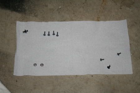
Ok so to start, you need the following:

Patience

12mm Socket

8mm spanner

Torque wrench (1/4" drive is best)

Rags

Plastic zip bags

Allen keys

Thick, wide flat head screw driver

Brake cleaner

Copper grease

Red rubber grease

Brake fluid (dot4)R

replacement seal kit for both calipers

Ok so here goes!

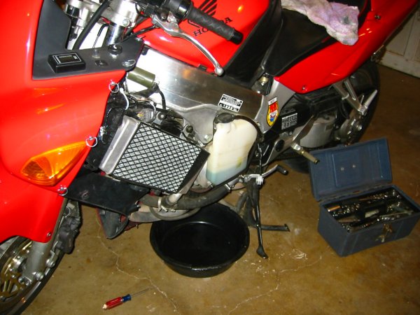
1. Prop the bike up. Centre stand, ABBA stand etc...just get it upright.

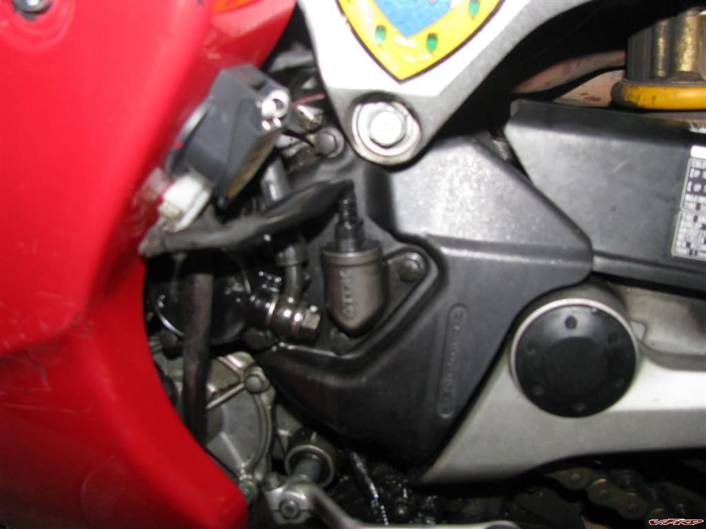
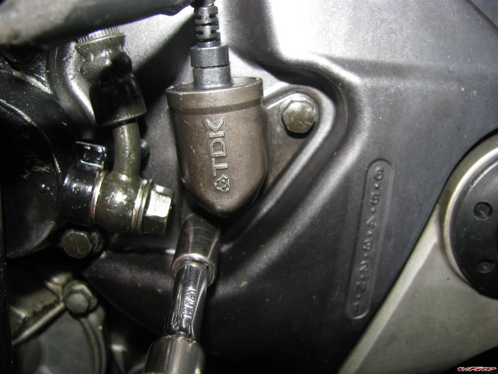
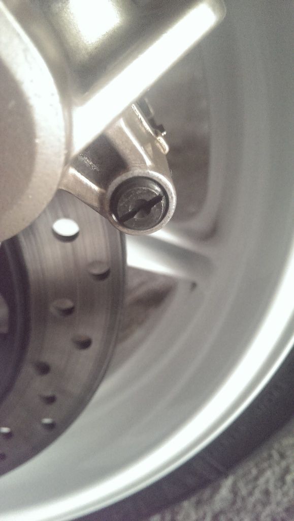
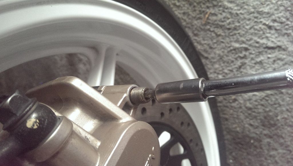
2. Remove the Pad retaining pin cover. *WARNING* this thing is a piece of sh*t, it can and WILL round off and be an arse to remove. I highly recommend you carefully select a fat, wide flat head screw driver tip and gently apply more pressure when trying to turn it. If you get the SLIGHTEST hint of the blade digging into the cover's metal, stop. Buy some decent penetrating fluid (WD40 fast action release is good) and douse it, leave it overnight and try again the next day. If it's truly stuck, try an impact screwdriver or just drill the bast*rd out.

IMAG1438_zpsevrxygmg.jpg

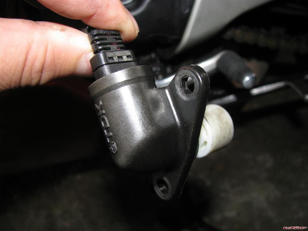
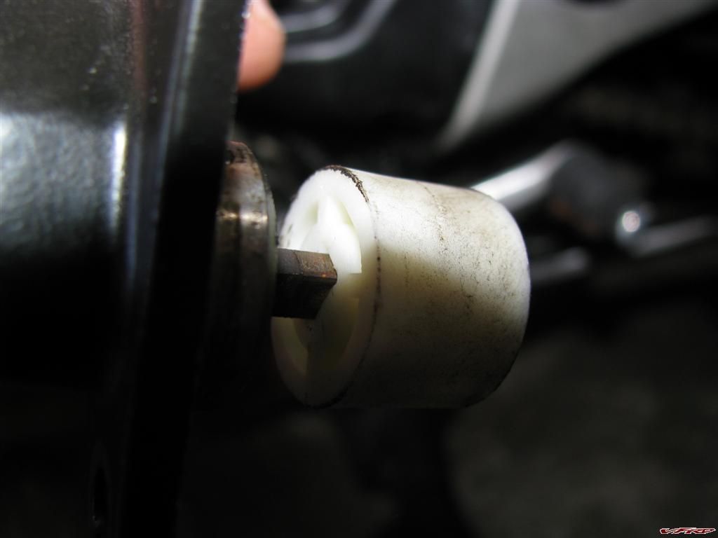
3. Remove the pad retaining pin

IMAG1439_zpshj0nlkvn.jpg

4. Remove the pads by giving them a tug if they don't fall out

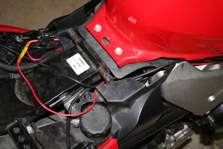
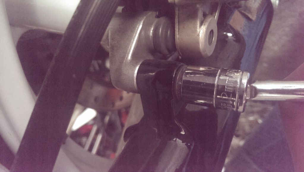
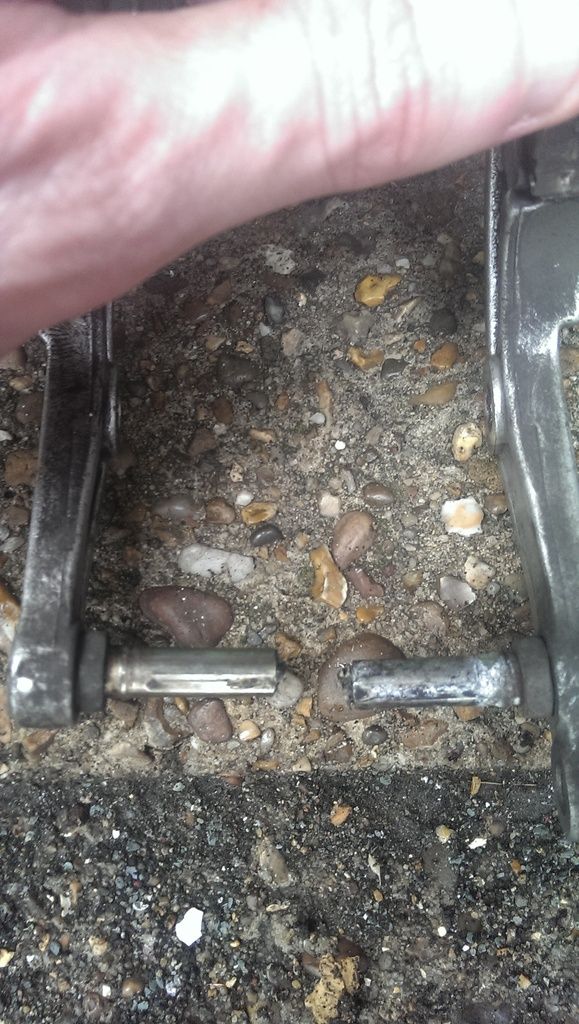
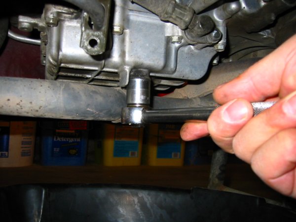
5. Remove the Caliper retaining bolts (12mm)

IMAG1440_zpsyihjoedw.jpg

6. Remove the calipers

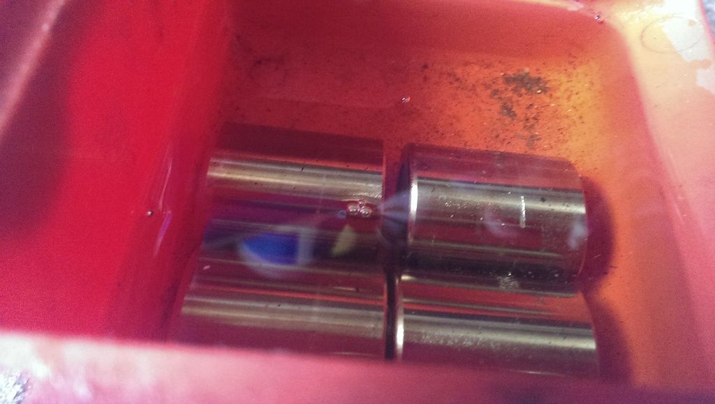
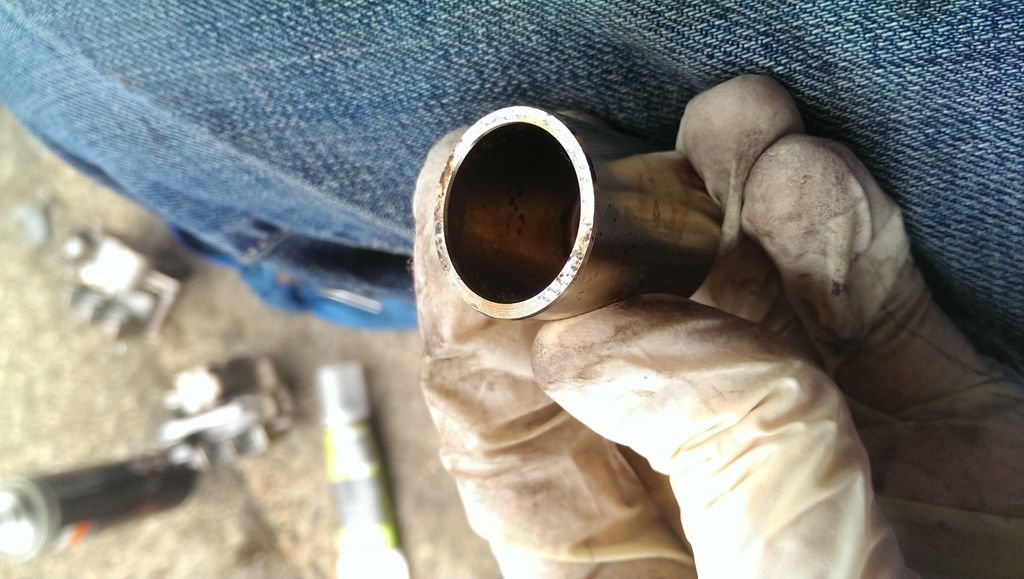
7. Place a piece of wood or something similar between the pistons and the inside of the caliper. The idea is to pump the brake lever until the calipers are MOST of the way out, so choose your piece of wood (etc) carefully. I actually used a plastic box that holds my digital measuring calipers! This will ensure the pistons move to an even point. You want them to be about this far out (see top piston, I later evened it out by pushing the top one back in, putting the plastic case in place and pumping the lever again until they were both out the same amount....

IMAG1441_zpsijsbiwph.jpg

8. Put the calipers back in place on the forks, loosely put the bolts back in to hold them there. You may need to push the slider part of the caliper out a bit to make enough space. Don't worry if the slider comes off the caliper, it just pops right back on.

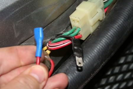
9. Place a rag under/around the caliper, specifically near the brake line banjo bolt (as you'll be removing this and will want to soak up the excess fluid. It EATS paint, don't wanna ruin your wheels...right?)

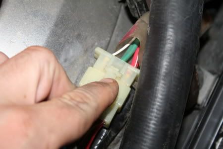
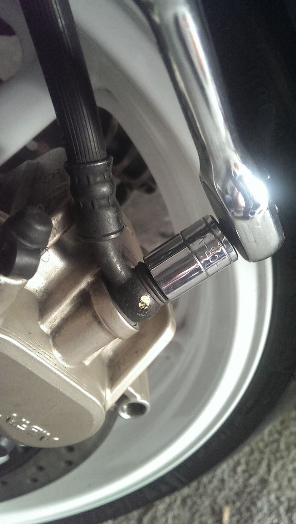
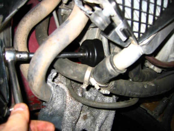
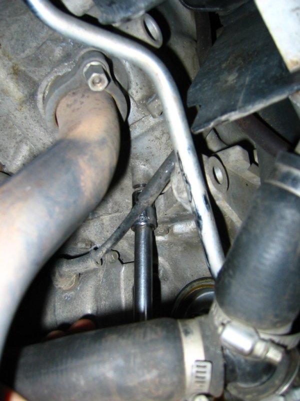
10. Use a 12mm socket to crack off the banjo bolt

IMAG1442_zps6m8hahbf.jpg

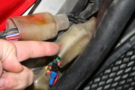
11. Make sure to hold the rag tactically to soak up the drips. Remove the brake line..try to leave the bolt and washers in place for ease purposes. Slide them back through the brake line etc if anything falls off.

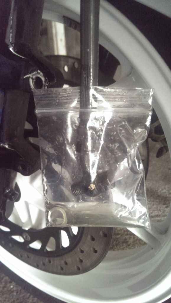
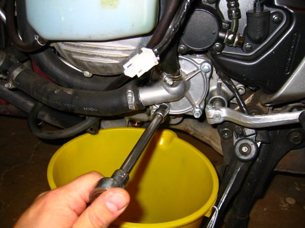
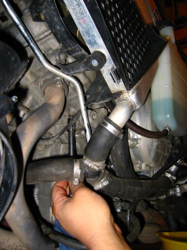
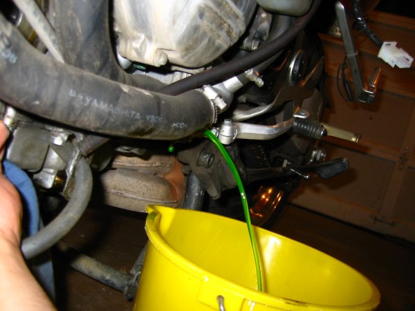
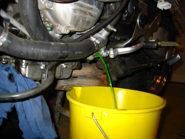
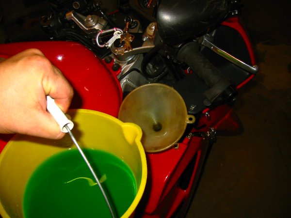
12. Immediately slide a plastic zip bag over the brake line. This will allow you to leave it dangling while you work on the calipers. *WARNING* keep the calipers upright so the hole that the bolt went into for the brake line is facing the sky. You'll spill fluid everywhere otherwise as it sits in the caliper. Pour it into a bucket etc by turning the caliper upside down.

IMAG1443_zpstw3snvdd.jpg

13. By the point the calipers will be off the bike and your hands will be all slimey, give them a wipe (your hands and the calipers!)

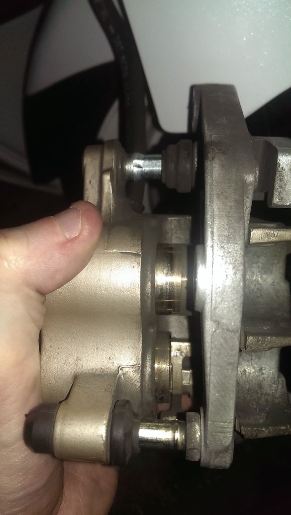
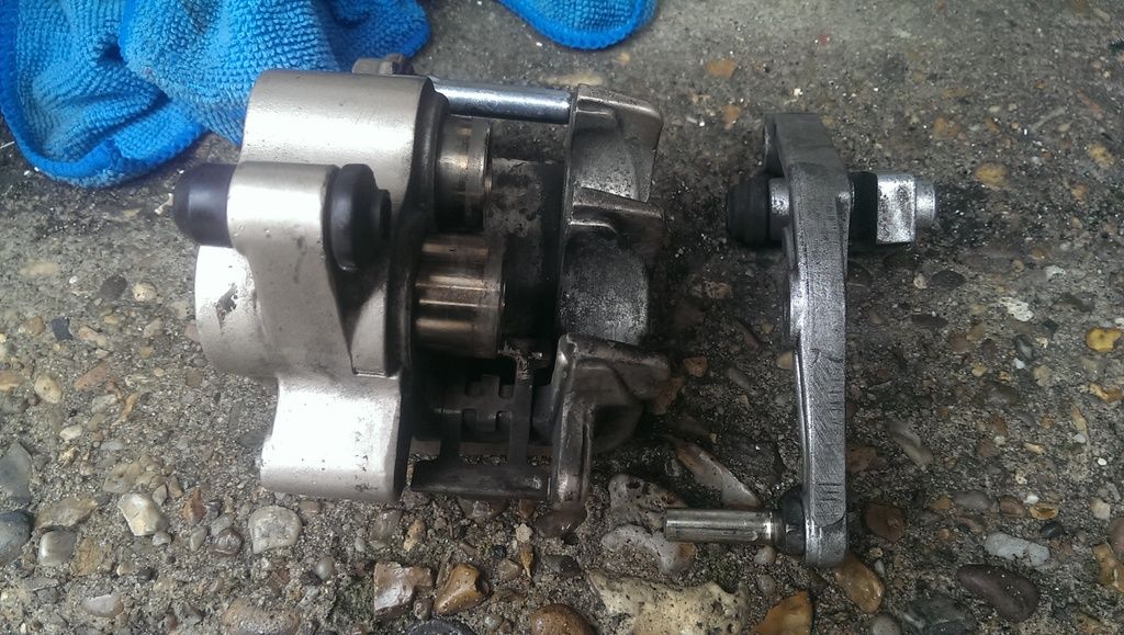
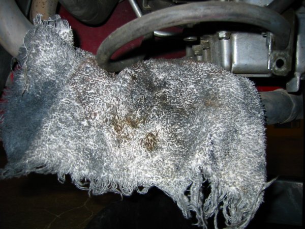
14. Pull the sliders off the caliper. You'll be left with the below

IMAG1444_zps2swhxyv2.jpg

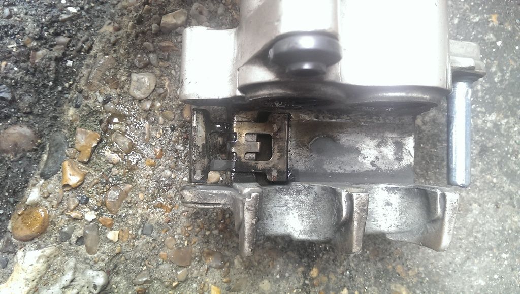
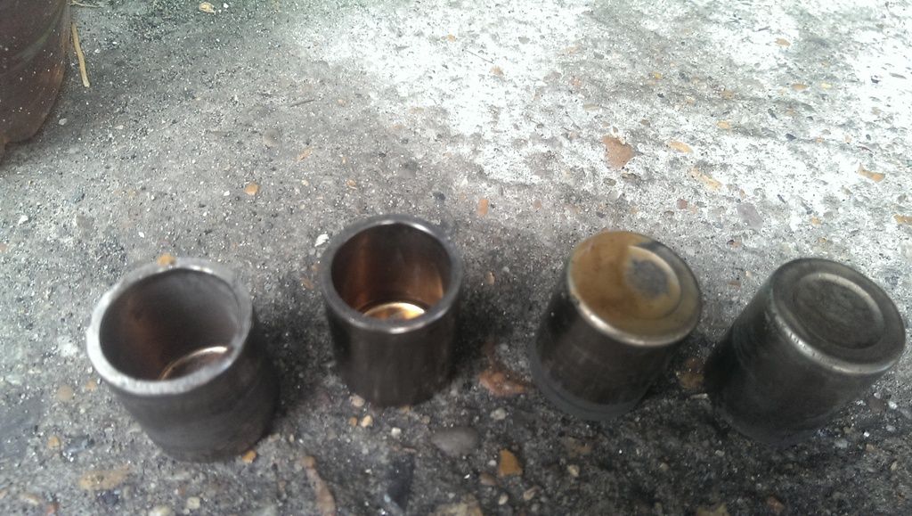
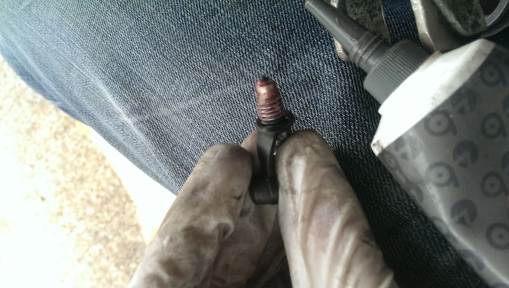
15. Get a rag, drop it over the pistons. Use some mole grips/strong pliers to grip the pistons over the rag and pull them out. Depending how badly seized your pistons are, you may need to use an airline in the banjo bolt hole to blast them out. Be patient and don't lose your cool, jump in the car and take them to a garage to blow 'em out if needed!

IMAG1445_zpsunr4qhcv.jpg

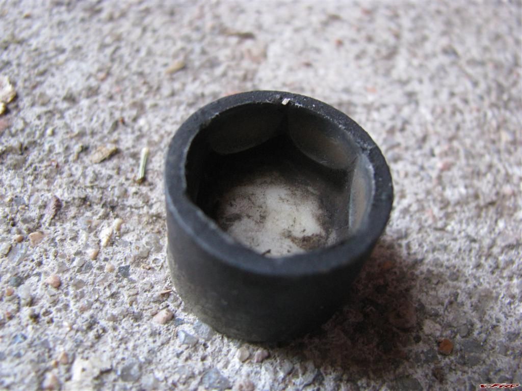
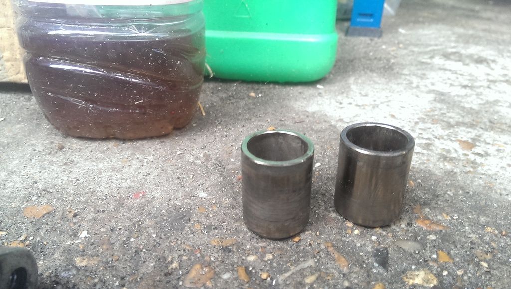
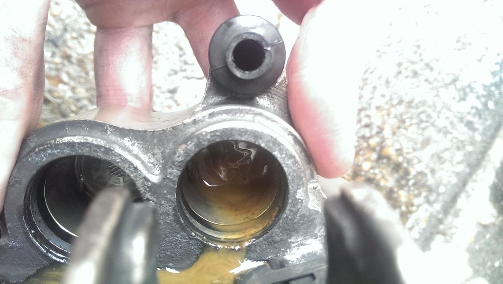
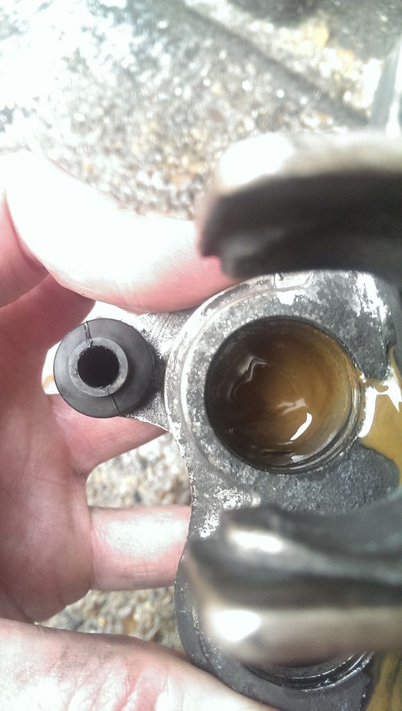
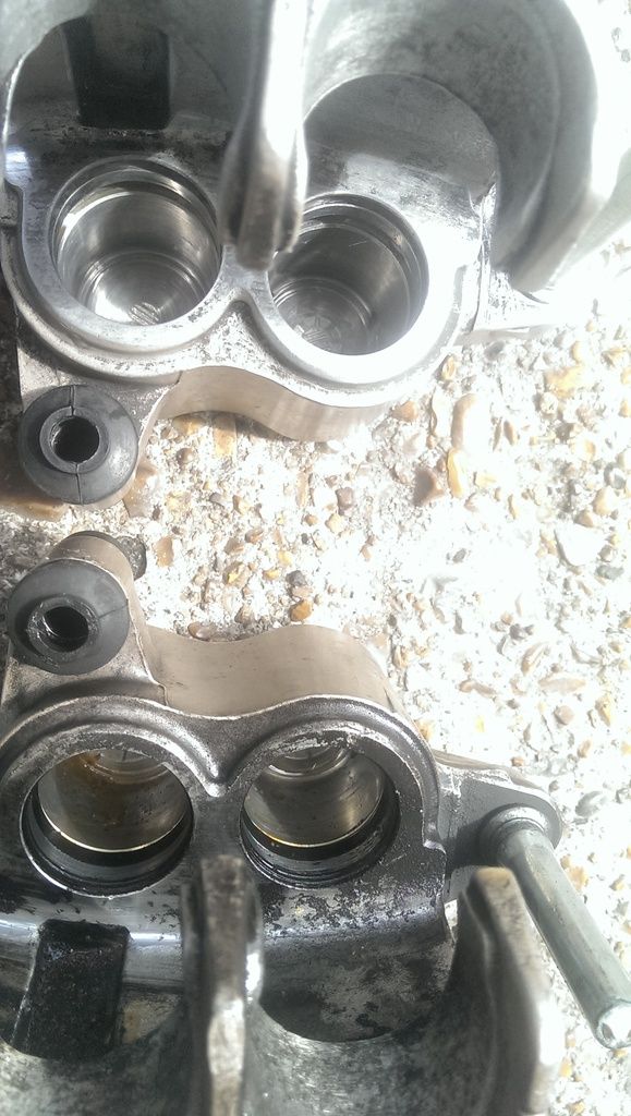
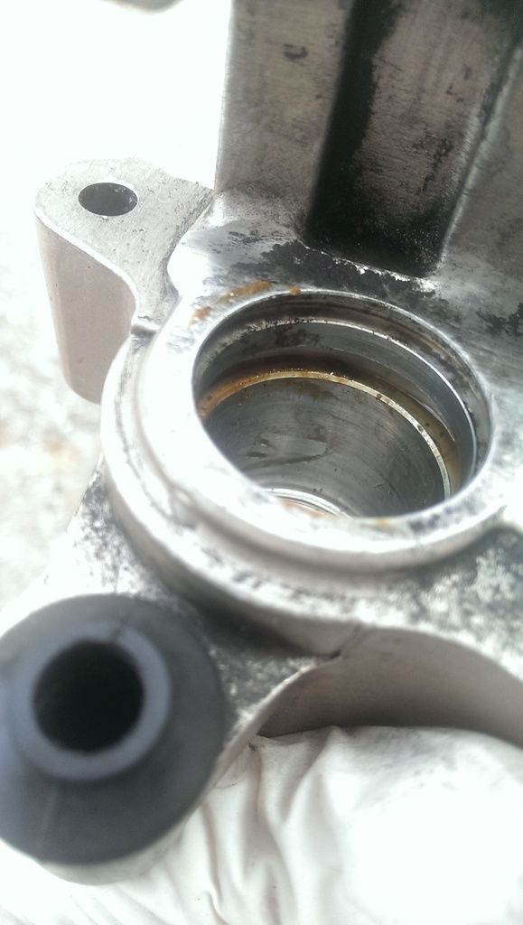
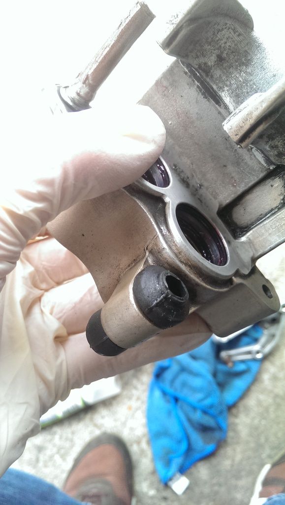
Now you'll be left with two empty calipers that are still dribbling fluid, just mop it up as best you can. If you think your calipers are clean...think again, they'll likely have rust on the sliding pins and or some horrible poo looking gunk in the piston holes. My bike has 25000 miles, has been incredibly pampered it's entire life (the service history folder weight about 5kg). Look at the different between one slider and the other, look at the gunk in the piston holes and on the piston itself. I flush my fluids every 3 months (excessive I know) and it still gets like this!

IMAG1447_zpslkbi8i8v.jpg

IMAG1448_zpskroo787n.jpg

IMAG1449_zpsjht7ok2i.jpg

IMAG1450_zpsk4ogjme3.jpg

IMAG1453_zpsp8bhyzvf.jpg

I've put my pistons in Paraffin so they can soak overnight to make removing the stuck on crap easier. You can get away with using super fine sandpaper to remove anything jammed on, but why ruin that nice smooth surface?

IMAG1455_zpssluiwqdl.jpg

Next thing is to clean the calipers up and replace the seals.

15. Clean all gunk, muck and poo from the inside of the piston holes and the surfaces of the calipers. I used a mixture of old cloths, brake cleaner and paraffin. As you can see above, my calipers were super mucky, all that brown shit was old brake fluid, that's what happens when you ride all year and leave it laid up for a while, this bike was off the road for five years before I purchased it! I went from this:

IMAG1450_zpsk4ogjme3.jpg

To this (top caliper is the clean one, bottom caliper was done shortly after)

IMAG1465_zpsemygqwuq.jpg:

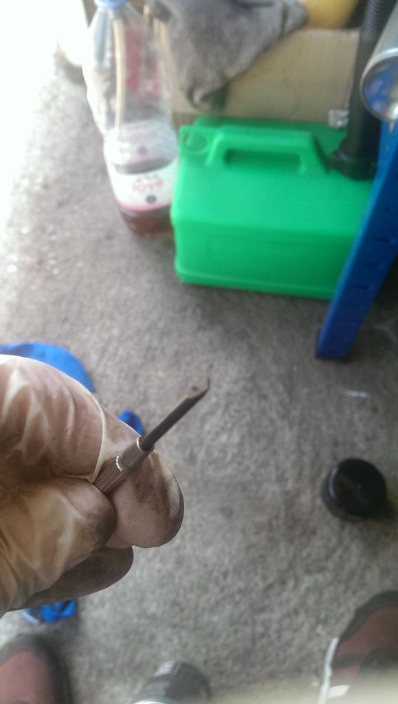
I had to use a very slim screwdriver with a cloth over the end to jam in the brake line hole, it had brown poo in there as well. It was so hard to shift that I ended up using one tin of brake cleaner per caliper!

IMAG1461_zpsmc3xzglp.jpg

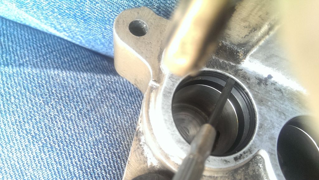
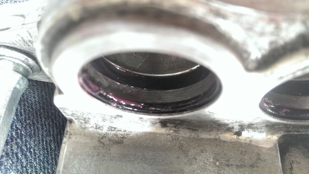
16. Next remove the seals, thin ones higher up the piston hole, bigger one further down. I used the same small screwdriver to remove these. They can be a pig so have a scalpel/something sharp to hand s you can stab and drag it out if it gets stuck

IMAG1462_zpsdoclslvy.jpg

The muck under the seals was pretty bad too. It works it's way past the seals over the years

IMAG1464_zpsfgubz4uw.jpg

Use the same small screwdriver or a tooth pick to scrape out as much of that crap as you can, you'll never get it all out unless you have an ultrasonic cleaning bath with some serious cleaning solution

17. Once cleaned, replace the seals with new ones or reuse yours if they're in good condition. I smother mine in red rubber grease before they go back into the slots.

IMAG1470_zpsx1rqesqh.jpg

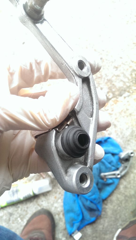
18. Now replace the rubber boots. The one on the slider part is easy to pull out. Give it a clean in there with brake cleaner, rag and screwdriver if needed. Replace the boot with a new one or reuse if in good nick

IMAG1473_zpsh5yovm1i.jpg

The caliper rubber boot is...awkward. It requires a lot of squeezing the end and tugging, It might split if in poor condition so make sure you have a replacement if needed, might be worth checking this in advance

IMAG1474_zpsbxk0bwva.jpg

19. Clean up your pistons and place them back into the piston holes. They can be fiddly so have a c-clamp on hand if they won't go into place. Again, I coat these in red rubber grease, it just helps the sliding action, is brake fluid friendly and keeps things from seizing for much longer

IMAG1475_zps7otguoyk.jpg

20. At this point I remove the bleed nipple and blast it with brake cleaner, both outside and jam the brake cleaner tube into the nipple hole and blast it out (watch your eyes, seriously!) I then coat this in red rubber grease and put it back in place

IMAG1469_zpswhazsrdq.jpg

21. Cover the sliding pins in red rubber grease, I previously assume coper slip was fine but it seems I was wrong. Grease on the pins keeps them from rusting and assures they take an age before needing another clean

post-4110-0-42566500-1439678922.jpg

(Thanks to Steve27bha for the above pic)

22. I now put the brackets back in place, they only go in one way so won't bother with a pic (forgot to take one anyway)

23, Out the slider back onto the caliper body, again these only go in one way so don't worry about what goes where

24. Brake pads now go back in place. I clean up the retaining pin with some wet and dry, feel free to coat it in copper grease to protect it from the elements

25. The brakes are now back together and ready to go on the bike, bolt them in place

26. Get a rag and wrap it around the base of the caliper, take the brake line out the plastic bag and put it back on the caliper, a washer sits at both the bolt head and under the brake line

27. Torque everything up (low range torque wrench should be in the region of £25):

Mounting bolts: 27nm

Banjo bolt for the brake line: 35nm

Bleed nipple: 17nm

28: bleed the system, wrap a rag around the master cylinder. Use a number 2 philips screwdriver/bit and remove the lid screws. Gently prize out the plastic cover and remove the rubber reservoir fill. Turn the wheel to the left if on a stand to level out the reservoir (Careful does it, don't spill anything as brake fluid eats paint remember)

Get an 8mm circle spanner, put it over the bleed nipple - either caliper is fine.

Some say do the one furthest away from the caliper first but I've found it makes no difference on these calipers. It does, however, on normal 2/4/6 pot calipers with no slider in my experience

Buy a one way bleed valve. Halfords sell these for £9.99 http://www.halfords.com/motoring-travel/motorcycling/motorcycle-accessories/gtmoto-brake-bleeder

Stick the spaner over the bleed nipple bolt

Dab red rubber grease around the nipple to stop air inducing into the system

Put the thin tube of the brake bleed kit over the nipple, the valve has an arrow on it that should be pointing away from the nipple/caliper. It's one way so stops air going back up the tube.

Now at this point your system will be all air and little fluid. So you WILL need to employ a traditional method of getting fluid through the lines and into the caliper (keep a bottle of dot four handy to top the reservoir up, don't let it empty of you'll induce air into the system and have to start all over again):

with the bleed nipple closed, pump the lever slowly four times, hold the level all the way in

open the bleed nipple with your other hand (this is why a circle spanner is handy rather than an open ended one as it stays in place) you only want to open the nipple a small amount.

Still holding the Brake lever in, close the nipple

Repeat the above steps until fluid starts to make it's way out the tube. It took me about 4 sets of 4 pumps. As long as everything is torqued correctly, it should be the same for you too.

Once fluid comes through, you can leave the nipple open for longer but will still need to close it from time to time to pump the lever four times (and hold it) to force air out the system. This induces pressure in the system. Once the fluid comes out clear with no bubbles, move onto the other caliper. The second caliper is never as hard as most air is forced out the first caliper and fluid starts to spread evenly,

Keeping a rag handy to quickly clean up spillage...

Once you're happy with the pressure on the lever (should stop about half way from fully disengaged to pulling it to the handlebar) fill the reservoir up until the fluid it just above the viewing glass. Now put the rubber filler back in place, then the plastic cover then the metal lid (the writing on the metal lid should face you)

Arguably you're done at this point. But roll the bike forward and press the brake. Careful not to drop your pride and joy - the bike should stop hard and the front dive a little.

You may find the brakes are a bit faded at first, take it for a slow spin around the blocks and progressively press the lever harder and harder until the bite feels great. If it simply won't bite hard you can check the following:

Pads for grease.dirt - clean with brake cleaner

System for air - bleed again until satisfied

Worst case scenario you may have a master cylinder that needs a rebuild, having a seized piston can mask this and make the brakes feel super tight and strong. Cleaning them up and freeing the pistons up to move evenly can show your system to be a bit spongey as everything moves back to positions as it should, rather than one piston staying 3/4 the way out while one backs off - or the slider being stuck as a certain point. Hope this makes sense.

I'm going to re-read this a couple of times and make alterations as I see fit. Hopefully it'll help those who're too scared to try this on their own. It's very easy as long as you're methodical about it.

How the fast idle wax unit works

PSA - K&N oil filter Failure

$
0
0

My K&N oil filter that i had hand tightened, failed at the weld while ridding. Not a drip but pouring out. I was lucky, i was sitting at a traffic light a mile from home and someone pointed it out to me. it was flowing so much i thought it was a radiator hose leaking, so road home carefully watching the temp gauge, when i pulled in realized it was oil and had coated my rear tire.

Paint care Products.

$
0
0

After many years of using various high quality polish products on my VFR's I feel I've really struck gold with this one. All my motorcycle buddies know how fussy I am with my bike apperance!

Not sure if its available overseas and ok, it is an Australian product(no commercial gain to me). It's just the best and easiest I've found to date.

Bowden's Carnuba Body Wax.

This product goes on and off sooooo easily AND leaves no annoying white polish residue on your seat or any other black surface.

Bike photo, just given a quick once over polish with this stuff.

Cheers.:fing02:


20210109_123819.jpg

SCA_323485_hi-res.jpg

5th Gen rear axle & swingarm bearing inspection at 60,000 miles

$
0
0


I feel that inspection of the rear axle and related bearings is an important but commonly overlooked  practice.  I wanted to do this earlier, but getting into this kind complicated assembly was a little daunting for me, so I put it off.


I was in need of a new rear brake rotor install that would require the rear axle to be removed from the bearing block.  While everything was out in the open, this was the time to closely inspect the axle/bearings for wear.  Bearing removal from block for cleaning and repack also was on the agenda.


Examining the cleaned axle, I see that the wheel side needle bearing axle race (the axle itself is the inner race) was in great condition.  I had added grease to that bearing 24,000 miles earlier, so everything was good at that end.


Taking a close look at the axle where the radial bearing lands, I see signs of the axle spinning in the race (SITR) of the radial bearing.   It was not a horrible spin out, but not good.  After rotating the bearing, I see why this happened.  It was very stiff to turn, like the grease was petrified between the ball bearings.  After 22 years/60k of service, it’s not surprising the grease is hard.


It looked like, if left alone, an axle failure was in my near future.  Lucked out that I found this issue before it all turned red hot and possibly seizing.


An option at this point if the damage to the axle is too extensive to overcome, you can buy a new axle from Honda for about $180.  Wheel lug studs are included.   This is a deal when you look at how much machine work there is on it.  Also, the bearing block loaded with bearings and seals is available for about $230.  For $410 your problems easily fade away.


Decided to move forward and disassembe the bearing block to see what it needed to be safe again.


If you decide that inspection is something you want to do, the following may be helpful.


The manual describes the disassembly/assembly procedures well, but here are a few things that may take a little mystery out of the process.


You will need access to a press for removing/installing the bearings into the block.  Luckily I have a friend that has one in his shop. The problem with pressing the bearings in and out is finding the correct drivers.  Getting creative here is helpful.  There are two different size drivers for removal of the bearings.  For removal of the smaller radial bearing we found a socket with correct diameter.  The other, larger needle bearing needed a driver slightly larger than any socket we had, so we belt sanded a 3mm washer to correct diameter & a close diameter socket to push the needle bearing out. 

image.png.9566c2b5918dce2028ee4021dc908853.pngimage.png.6482a0c9b5fa831cb7c49e169257166d.png


Before you can press the bearings out, you will need to remove the dust seal and a bearing keeper ring.  The ring that is holding the bearing in the bore creates a space between the bearing and the dust seal.  Use this space to get a screwdriver underneath the seal and lever it out undamaged.


Now you need to deal with the small keeper ring.  The ring has no clip holes for a keeper removal tool.  It requires the use of a pick or micro screw driver to remove.  One came out with moderate effort, but the other one challenged more than a couple peoples patience.  Before I put it all back together, I took my dremel tool with a micro round cutting bit to carve a tiny channel that will allow the micro screwdriver to get behind the ring.  This access channel is still covered by the dust seal when it is installed.  This just makes it easier to access next time.


The first bearing to come out is the radial bearing.   Once pressed out, you see it is actually two narrower ball bearings joined together with a plastic ring with one grease seal on each to make a sealed bearing when they are together in the bore.  Being able to split them allows the bearings to be cleaned/inspected and repacked if deemed worthy.

image.png.b68fd6f114974013545cfb2bad29e612.pngimage.png.92f4cdd8e87e8900897f8221a54c32da.png

After cleaning the bearings, I think they are still good to use so I packed them both with some moly grease.  Seals looked ok so they also went back in.


At the bearing installation step, a 62mm driver installs both bearings.  Since they are both the same diameter, make sure you verify the correct position of the bearings before you press them in.  The needle bearing has a built in oil seal that needs to be facing the inside of the block.   I have a 1 13/16” socket that was 1mm too big in outside diameter for use as a install driver.  After belt sanding it down to proper diameter, I now have a installation driver that also doubles as the socket for the rear axle nut.


Install both bearings in their respective bores, install the keeper rings, then the seals.  


There is a sealed bearing in the sprocket drive plate.  If the bearing feels good, no need to take it out.  This bearing deals with the movement on the drive plate interfacing with the damper plate.  Not much movement here.  And BTW, I put in a new rubber damper set while there. 


With the bearing block back in the swingarm, the axle got put back in for a test fit.  Even though the radial bearings have been cleaned, repacked  & are spinning easier,  the axle still spins easy in the bearing race.  This SITR condition cannot be tolerated.  Bad things will happen if not resolved.


I have dealt with this SITR condition in trailer axles in the past.  One solution is to take a center punch and lightly install some divots. This creates a raised crater effect that, in my case, increases the diameter of the axle at the radial bearing landing.  I just happened to have a spring loaded center punch that made the perfect size indents.

image.png.da513b5e9ffd49233bfe1adb622e5301.pngimage.png.6f7966d178924adedfc79b9e7d12426f.png


I put about 25 divots for each of the radial bearing landing areas.  Cleaned the inner races and axle area free of oil, applied blue threadlock to the axle bearing meeting area then installed the axle.


The divoting made a fit that required me to use a mallet with light force to push the axle through the radial bearing.  I think it is the perfect fit and coupled with the threadlock, I won’t have a SITR issue here again.  I will have to use a little force to remove the axle if needed in the future, but not too much.


At final install of axle assembly to the bearing block, the axle nut requires 148 ft/lb torque.  Rather than using the brake to hold the axle from turning, a lever through the lug studs is much easier.

image.png.a3e51ac227b9942db5bdacc650e0d544.png


I let it all set for a few days to let the treadlock firm up.  It now looks like SITR issue now history.  I can check the bearing block for heat at the radial bearing area occasionally without removing anything for hints of any future failure in progress.


If you don’t need to wait for new parts and are able to reuse what is there, the time it takes to remove the bearings from the block, clean them, repack, and reinstall would take about an hour.


While up on the rack, I also got around to…

>Shock absorber removal, sent to Jamie for revalve & new spring. New pivot bearing & pin

>Removed the swingarm for pivot bearing inspect. All good.  Added moly grease.

>Installed new rear brake rotor and pads

>Removed counter sprocket cover and thoroughly cleaned the area.

>Installed speedbleeders then replaced all hydraulic fluids.

>Initiated Fritzers famous chain cleaning & maintenance procedure J

>Oil and filter change

image.png.1333a1e4c076d587227efb55017c3f69.pngimage.png.de30cc641ccccad36e2859820b01a1d9.png


Bringing an end to a very long story, it leads me to my final point.  If you have a high mileage/age VFR, it might be wise to open the axle/bearing block assembly for inspection/maintenance.  I think this SITR condition could be common on high age/mile bikes.  Once you have gone through the procedure, you realize it is not that big of a deal to do again in the future.  Major piece of mind knowing your rear axle is up to the task.


Sliders

$
0
0

Hi, today I just bought sliders for my VFR 2002. I already knew about cutting side fairings, but maybe anyone has a picture of where directly I should cut them? And what best option - modification for a coolant tank? Thanks

v4dreams.com website

$
0
0

I am not sure if this has been posted before but I just came across this website dedicated to the VFR (primarily the second-gen 1986-87 VFR 700/750), and set up by a VFR enthusiast by the name of Joe Nelson. I would be surprised if he isn't a member of this forum. Some useful articles, some (possibly hard to find) parts, an interesting Blog, and some history on the VFR


Maintenance - v4 Dreams


Controls Lubrication

$
0
0

While I was working on my VFR, I bought (and have sold) a 2018 motorcycle. The handlebar switches were so smooth and crisp. I would like to renew my VFR to those levels. I understand I'll need the disassemble/clean/lubricate the internal components. 


Are there recommendations on cleaning agents? What is the best lubricant to use to renew these parts?

Feel free to add anything I may have overlooked.


Thanks!

Radiator flush & oil change

$
0
0

Oil Change and Radiator Flush

I began by first removing the 2 lower fairings with the bike on the center stand.

First I drained the oil, position the drain pan below the oil plug.

flush01.jpg

The manual says to warm up the engine to get the oil to flow better, I don't do that since I like my skin unburnt, I just let it flow out for a very long time! Remove the drain plug 17mm, Inspect it for pitting the soft metal washer might need to be replaced if it is pitted.

flush02.jpg

When replacing the oil filter it is best to put a rag over the headers cause oil always spills out onto them.

flush03.jpg

It is difficult to remove the oil filter by hand or using a ring type wrench, I use this Honda filter wrench $7.00

flush04.jpg

flush05.jpg

I removed the old filter but did not replace it yet since I need the room to do the radiator flush. I did however replace the oil plug.

Flushing the Radiator

Remove the drain plug from the water pump, make sure the bike is not hot! You will get burned! The bike was cold here, the fluid will not come out until you introduce air into the system.

flush07.jpg

I drained the cylinder plug now, you can see why I did not put the oil filter back on, because it was in the way, make sure your bucket is positioned cause the old antifreeze squirts out about a foot and a half.

flush08.jpg

Here is a better view of where that plug is

flush09.jpg

It just starts gushing out, once its almost done go over to the other side of the bike and open the radiator cap, more will come gushing out.

flush10.jpg

radiator cap open now

flush11.jpg

At this point I began pouring in distilled water into the radiator cap, and watched until the fluid coming out was clear!

  • put both drain plugs back in
  • screw on the oil filter 7ft/lbs
  • screw on the oil plug
  • fill the oil up 3.5 quarts approx
  • fill up the radiator with distilled water
  • start the motor till it warms up then turn it off
  • wait until it cools down
  • check the motor oil level top it up to the level in the sight glrear
  • remove the drain plug and radiator cap and drain out the distilled water

Once all the water is removed from the radiator replace the drain and mix the antifreeze.

I used simple ethylene glycol, Wall-Mart brand, its aluminum block radiator/motor safe, and it contains no silicates, you don't want to use a brand that is not rated for aluminum engines. Silicates can damage your water pump, most major brands do use silicates so read the label. You can use the Honda brand, its made by the same company that makes Citgo gas (Seven Eleven stores brand), Citgo also makes the Honda brand oil. The Wal-Mart stuff is fine, aluminum safe and no silicates (read the owners manual its all there).

I mixed it 50% antifreeze and 50% water, that 70/30 is the best concentration for the greatest temperature extremes. 50/50 is as low as you want to go but gives the best cooling in the summer. DON'T USE TAP WATER the minerals will build up and cause blockages, use distilled water.

I poured it in my 50/50 mixture about a gallon till it filled to the brim of the cap, I also poured out the overflow fluid and replaced it with new fluid in the over flow jug.

put the cap on start up the motor and rev it a bit, turn it off and check the level again, top it up if need be.

flush12.jpg

A word about oil

I usually change my oil about every 3000 miles, when I do I always change the filter too, I don't use expensive synthetic stuff since that oil is designed not to break down over longer periods of time, if you change your oil as often as I do the oil is usually still fairly clean, its a waste of money to use expensive oil. As long as it is the right weight 10w 40, no molybdenum or graphite additives as it harms the wet clutch. They say your oil does not need additives, don't use castor based, or non detergent, vegetable oils!

Also since your riding a bike that has a wet clutch the friction plates of the clutch are soaked in oil, you want to change the oil often since the friction material of the wet clutch wears off and circulates thru the filter, don't wait more than the recommended 6k miles to change it.

NEW! Bleeding/fluid Replacement On Linked Brakes W/abs On 6Th Generation (The Ultimate Guide)

Leaky fork :-(

$
0
0

Once again I find myself consulting the forums in search of a better solution, so thanks in advance for any advice/pointers. My left fork has decided to puke its contents after letting the local Honda Stealership replace the seals less than one year ago.  I've probably only put 600 or 700 miles on the bike since then under normal driving conditions so I don't understand why it's leaking.  Anyway the stealership has informed me that the bushings are worn and that is what is causing the leak.  I asked why the bushings weren't replaced 10 months ago along with the seals and all I got for a response was a shoulder shrug since it is a different service manager now.  In addition to the shoulder shrug I got a wonderful estimate of $1200 to fix the forks and bleed the front brakes to remedy too much lever travel.   $1200....😕  ?  I checked my calendar and it wasn't April 1st so I guess he was serious.  I have worked on my bikes in the past but have no experience with forks/suspension repair, so can anyone point to a comprehensive how-to vid or guide for a dummy who has been riding for almost 40 years but never messed with forks?  Thank you my friends.


Oh yeah I forgot:  6th Gen '05 VFR800 with ABS barely broken in with only 11K miles 😁

Coolant system flush and renewal

$
0
0

Hello All, 


Just did a thorough coolant flush and renew on my "new" 5th gen 1998 and set out the steps below. Hope it helps someone out. 


High mileage bike with what looks like poor maintenance. Thank God it's a Honda or it would be scrap by now. 


Anyway, I began by pulling the side fairings (I'm doing other work - you don't have to remove all the fairings like I did) and putting the bike on its side stand to drain the old fluid.


Note the extreme lean angle achieved by finding a nice dip for the side stand. You can also just muscle the bike over to the left whilst lifting the front wheel. Easier than you might think. I found having the bike on an uphill slope drained the most coolant. 


To to drain the system remove the "odd" 5th bolt and washer on the thermostat (right hand side, near your foot peg). Place a container underneath and slowly unscrew the coolant filler cap. Unscrewing the cap lets air enter the system and it flushes really fast. WARNING: this stuff shoots about 4 feet! 


There is also a coolant drain bolt under the front left exhaust downpipe which is awkward to reach but also dribbles a bit of fluid if you really want to get every last drop out. I did, but it may not be necessary on a well maintained machine. 


Finally, detach the hose from the overflow bottle on the left and let that drain. It just pulls off easily. 


In all, I only got about 1.75 litres (nearly 1/2 gallon) of fluid out. The bike takes twice that to fill so clearly a maintenance fail by PO. Coolant looked red and dirty. 


Now the technical bit. I replaced all bolts/hoses and refilled the system slowly with equal mix of distilled water and white vinegar. Vinegar helps remove hard water deposits and scale from aluminium and is used to clean coffee machines.


The engine was set to idle and vinegar mix circulated for a while to thoroughly clean the system internally. 


I ensured the thermostat kicked in and juice was fully circulated by waiting until the cooling fan kicked in. Another way to check is by massaging the cooling system hoses and feeling when they warm up. Or you can look down the filler neck and see the fluid flow. 


After it cools you drain the system again as described. Strong vinegar smell and coolant was full of crud that the acid had cleared out. Really happy with results. 


Now I had to neutralise the acid from the vinegar (don't want that corroding the aluminium) so I mixed up some Soda Crystals in distilled water and filled her up again. Soda is a base and will neutralise the vinegar's acid. Luckily soda is a buffered base so you can't add too much - it never overdoes it. I poured it through an old sock to filter out any undesolved soda crystals. 


Ran the soda water to full temp as before, let cool and drain. Weaker vinegar smell came out and the coolant looked like it had collected a bit more crud so I was very pleased. 


Next step is to rinse the soda residues out so filled the system up with 100% distilled water and ran it for some time. Let cool and drain as before. This time I poured a few jugs of distilled water through the system with the drain bolts out, just to flush straight through. 


Fitted new bonded washers to the drain bolts because someone had been a bit heavy-handed tightening them and I could feel the threads were damaged. The bonded washers seal easier than copper washers (don't need as much tightening) which gives the threads a break. 


Steel bolts into alloy is always a recipe for disaster so I do the same with my sump plugs. Really saves the threads. 


Ran a die tap over the bolts to straighten the threads and applied a light smear of copper ease. Good as new. 


Remember to burp you cooling  system by blipping the throttle hard a couple times and massaging the hoses. Cranking the bike over sideways also helps get air bubbles out. Pouring the coolant in slowly (no glugging) is also helpful. 


Now the the system is perfectly cleaned and I am confident in it once more. 


Happy days! 


Stray

IMG_4251.JPG

IMG_4179.JPG

IMG_4180.JPG

IMG_4191.JPG

IMG_4192.JPG

IMG_4193.JPG

IMG_4202.JPG

IMG_4252.JPG

IMG_4253.JPG

IMG_4177.JPG

Viewing all 78 articles
Browse latest View live