Quantcast
Channel: Maintenance Guides Latest Topics
Viewing all 78 articles
Browse latest View live

Gen 6 clutch issues

$
0
0

Hi, i just replaced the clutch disks, steels and springs on my VFR 800 vtec abs and have a weird issue


Before changing all this i had the clutch slipping, i had cleaned and replaced the clutch oil as had obviously never been changed and was disgusting.


I had replaced and bled the system and the clutch feel was much better but still slipping. The steels seemed warped but the clutch in good condition.


i replaced the lot as i wanted to start fresh, however not i have this issue:


bike on, i put the gear in, leave the clutch out, and it doesnt move, dunno if it's my imagination but if i leave the clutch out very very slowly i feel like it creeps forward but clutch slips.


Any ideas what to look at? slave clutch?

One note, when i was tighting the bolts on the pressure plate the plate would spin, i had to put a gear in, is this normal?


Thanks for any advise


VFR1200F - Centerstand Install

$
0
0

med_gallery_491_3604_555621.jpg

Center stand installed and lifting the bike up

These are the steps to installing an oem centerstand for a VFR1200F Part Number 08M50-MGE-100 This retails for around $200 delivered, I got mine from ServiceHonda.com. Before even attempting to do this MAKE SURE THE BIKE HAS COOLED OFF you will be working around the headers and you will burn yourself if its hot!

gallery_491_3604_495177.jpg

Centerstand parts and instructions

gallery_491_3604_724631.jpg

Inner and outter springs main spring and a safety spring that fits inside

gallery_491_3604_928962.jpg

Should the main spring break the smaller saftey spring inside will keep the centerstand up so that the centerstand does not fall during riding causing an accident

gallery_491_3604_119991.jpg

Bump pad wet with soapy water to install inside the hole in the stand

gallery_491_3604_223683.jpg

Twist and push on the bump pad until the pad seats itself inside the hole

gallery_491_3604_600533.jpg

Grease the post holes

gallery_491_3604_893714.jpg

Grease the other post hole

gallery_491_3604_380431.jpg

This is where you will install the center stand post goes inside that large hole and the spring hook in the upper smaller threaded hole

gallery_491_3604_1019078.jpg

I used Honda thread lock on the spring hook bolt I dont want it falling out

The bolt is a 14mm bolt and the torque spec is 16 foot/lbs

gallery_491_3604_18753.jpg

Dry fit This is the basic layout of the centerstand mechanism

gallery_491_3604_106895.jpg

Here I am trying to install 1 of 2 washers on the right side washer 1 goes inside the right stand post hole 2 on the outside of same post hole

gallery_491_3604_326819.jpg

I had difficulty holding the washer in place so I taped it in place with masking tape

gallery_491_3604_108896.jpg

washer 1 taped into place

gallery_491_3604_288894.jpg

I slid the post into the post holes fitting washer #2 was also a chore not much room with the headers there

gallery_491_3604_606273.jpg

side the cotter pin into the hole in the post right side fingers or use a needle nose

gallery_491_3604_523551.jpg

cotter pin goes here right side

gallery_491_3604_190257.jpg

spreading out the cotter pin ends is difficult to reach a flat head screw driver did the job from the front on the right side of the bike

gallery_491_3604_258503.jpg

installing the springs I used an old spring installer my Grandpa had for drum brakes - instructions call for two persons to install the springs

gallery_491_3604_249990.jpg

The safety spring did not go on the first time needle nose pliers for that

center stand.pdf

Brakes - Warped Rotor Fix

$
0
0

There have been a few post on pulsating brakes, one cause is a warped disk. It is not a very common thing with floating disks brakes because they float on a band of rings and the rotor itself is heat tempered. However a dragging brake pad can heat up a disk and warp it. I have been getting alot of pulsation in my brakes as I begin to apply them, I suspected the rear brake, it is difficult to tell, so I put the bike on the rear stand and turned it to see if it was rubbing, I could not feel any rubbing so I turned next to the front wheel. I jacked up the front wheel and this time I could feel the brakes rubbing as I turned the wheel, somthing was wrong.

There were several possibilties, due to the fact that it would only rub at a certain position, It could have been a warped disk or the axel was bent.

I dont have a truing stand so I used my handy dandy Miguel special, 2 jack stands a rod and a bunch of clamps, I have a dial indicator I bought for around $30 bucks some years ago when I was going to rebuild a car engine, I removed the wheel and set up a way to turn the wheel smoothly.

Here is my setup this is from behind.

runout05.jpg

It worked great, no false readings from the stands moving. The clamps worked well, I had my magnetic dial base on a heavy hunk of rail road rail.

I measured the right rotor first

runout01.jpg >

Here you can actuall read the measurements in the next picture it was within 0.010 inches of play (the service limit is 0.012")

runout02.jpg

The other rotor told a different story much more runnout and way out of spec! It was the warped one! 0.034" much more than the service limit

runout06.jpg

For good measure I tried a different measurement by taking off the bolts and sliding it where it was mounted, the measurements were the same.

runout08.jpg

I took it to the salvage shop, they did not have one in stock, but there are a few bike that share the same rotor for a 98-01 VFR, unfortunatly they cannont be machined, they must be replaced, I priced it out at $249 retail, and around $190 for discounted price, salvaged price varied from $120 to $175 ouch!!

CBR 600 F4 (99-00)

Valkerie GL1500 (97-02)

CBR 900 RR (93-94)

MFG: 45220MBG003

I recently tried prying a warped disk back into spec with a large crecent wrench, as long as the carrier is not bent out of shape the floating disk can be tweaked a bit one way or another to get it back in spec.

I tried it on my wheel balance station with the dial indicator there to show me where to pull or push on the disk, then run the wheel around and remeasure until its within spec.

It might warp again but a few times of this and it will stay, this will only work if its not too far out, and the carrier is not bent.

Fuel Tank Restoration

$
0
0

The Problem:

IMG_20230215_200853.thumb.jpg.b893d211d151a2918a30c678a53d88c7.jpg

If your tank has rust or needs a clean out, this guide is for you.  Although I used the POR15 kit in this guide, any similar products can be used (degreaser, metal etching acid or similar and a tank sealer paint), please follow the instructions for your products used.  This guide was performed on a VFR800 Gen 5, but the steps apply to any tank, with just the disassembly / assembly steps and specific bike parts, will be a little different.

Prep:

Required:

  • ·       20 Litres White Vinegar (Optional)

  • ·       POR15 Motorcycle Bike Fuel Tank Sealer Repair Kit (or similar treatment kit).

POR15.thumb.jpg.5ccf28f28f2652416c0599a2f88570fb.jpg
  • ·       A bunch of old screws/length of chain.

  • ·       A heat gun or hairdryer.   When it says dry the tank, it is always force dry using either the heat gun or a hairdryer.

  • ·       10mm socket or spanner.

  • ·       A long thin piece of metal like a brazing rod (if any of the ports are clogged)

  • ·       Dish soap.

DishSoap.thumb.jpg.0116109c831a2cc4c0794e64c830f17f.jpg
  • ·       A syringe

  • ·       2 metal or strong plastic plates , sized and drilled to cover the 2 bottom ports ideally.  Or anything that will seal the ports and not leak. (I personally used the bottom of a plastic paint bucket cut to size and sealed with silicone for the small port.  I used the fuel pump assembly plate itself as I was replacing it, for the large port, it was not ideal, but it sealed well).

  • ·       Duct Tape

  • ·       Bicarbonate of Soda (1 cup will do)


Parts List:

PartsList.thumb.jpg.cc725173a6c510e19b71eab3e6d33771.jpg

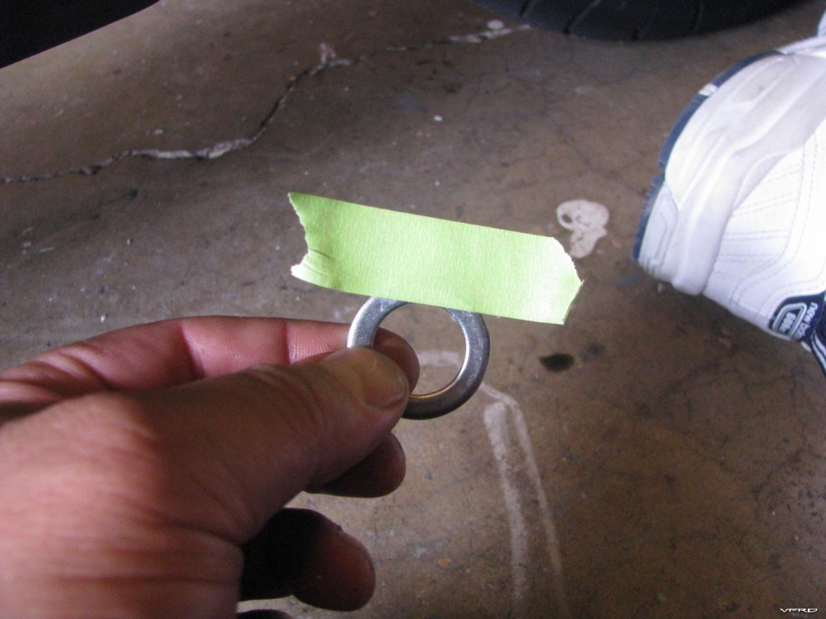
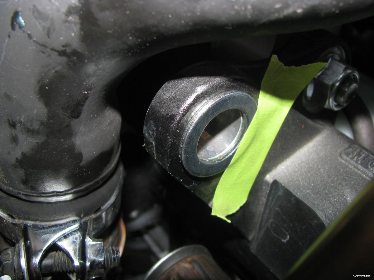
  • ·       91305-MC7-000 (for gen 5 VFR800, or equivalent fuel tank sealing o-ring).  No. 43 in parts list.

  • ·       17574-MN5-000 (for gen 5 VFR800, or equivalent rubber base gasket).  No. 23 in parts list.


Safety:

  •          Wear eye protection when using any cleaning/prepping agents.

  •         Perform all steps in an adequately ventilated area, ideally outside.

  •          Wear correct gloves for metal prep and degreasing stages.

  •           Follow all labels on chemicals used.

Steps:


Remove the tank:

1.       Run the bike until there is 1 or no bars on the fuel gauge.  You want to have as little fuel in the tank as possible.

2.       Siphon out any remaining fuel.

3.       Remove the seat.

4.       Remove the 2 front bolts holding down the front of the tank. (No. 50 in parts list)

5.       Prop up the tank with something.  I used an extendable window cleaning squidgy.

6.       Disconnect the battery.

7.       Put a cloth or similar under the tank area, to catch spills if any.

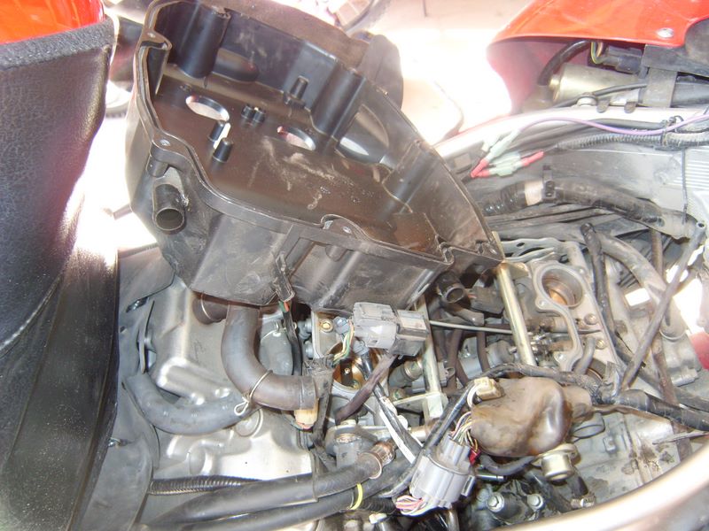
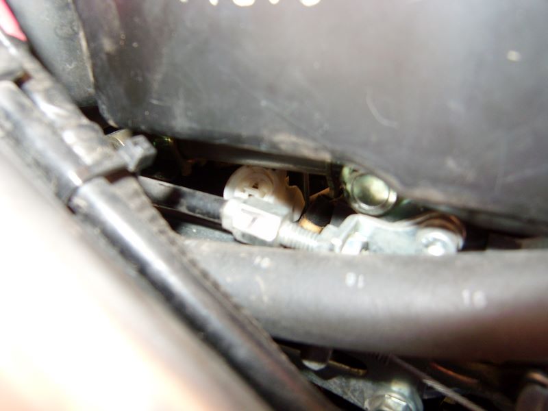
8.       Put the tank on its side before removing the supply & return lines

9.       Remove all tubing and electrical connectors from the bottom of the tank.  Wrap in cloth to avoid spills.

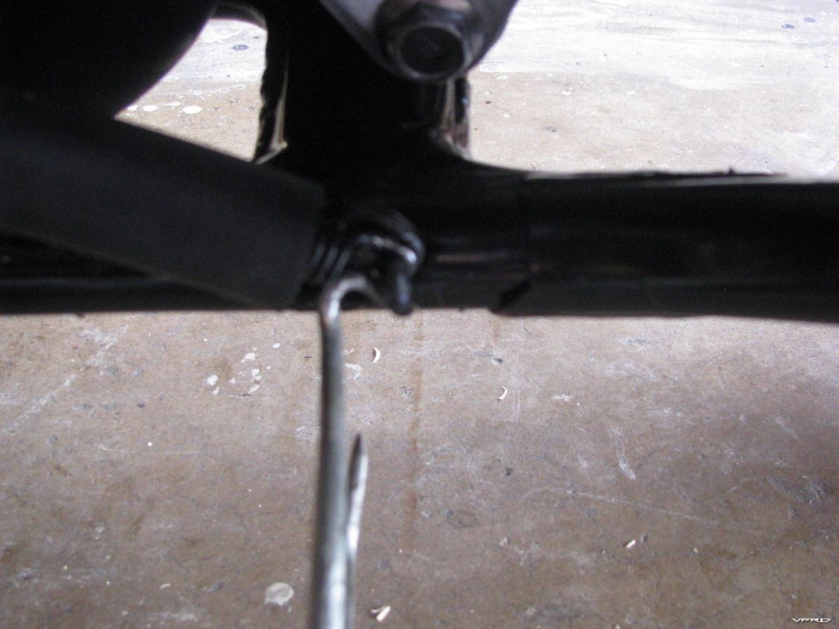
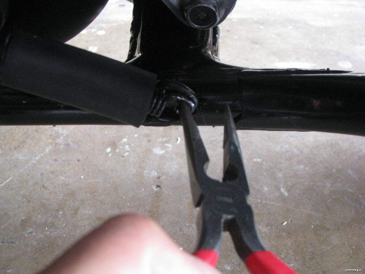
10.   Unscrew the 2 screws on the back of the tank. (No. 49 in parts list)

IMG_20230213_174538.thumb.jpg.ed81eb288038dd1f2fd560bdd40eb274.jpg


11.       Remove the tank.

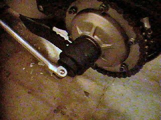
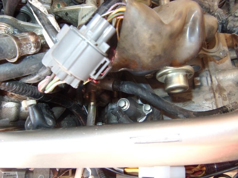
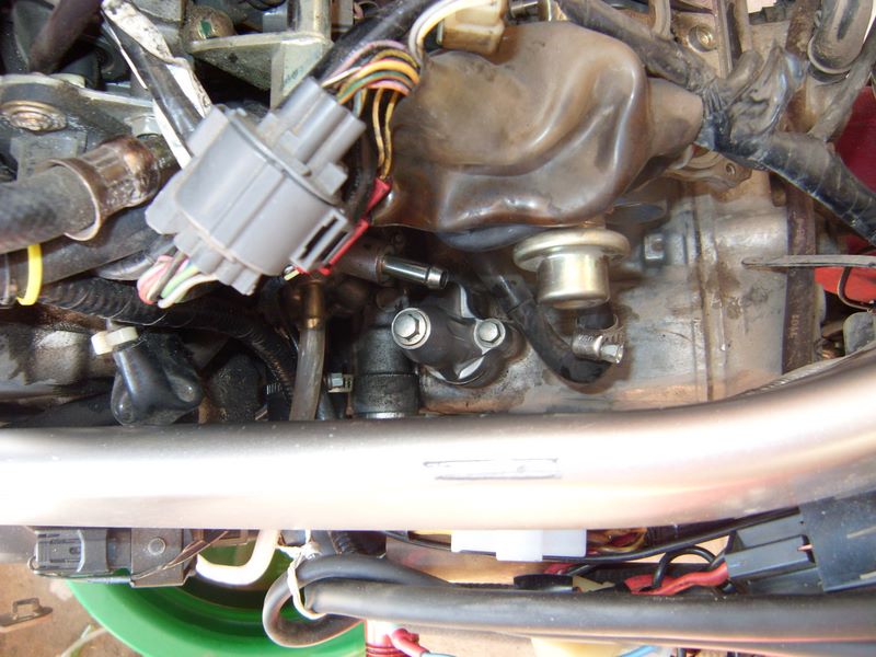
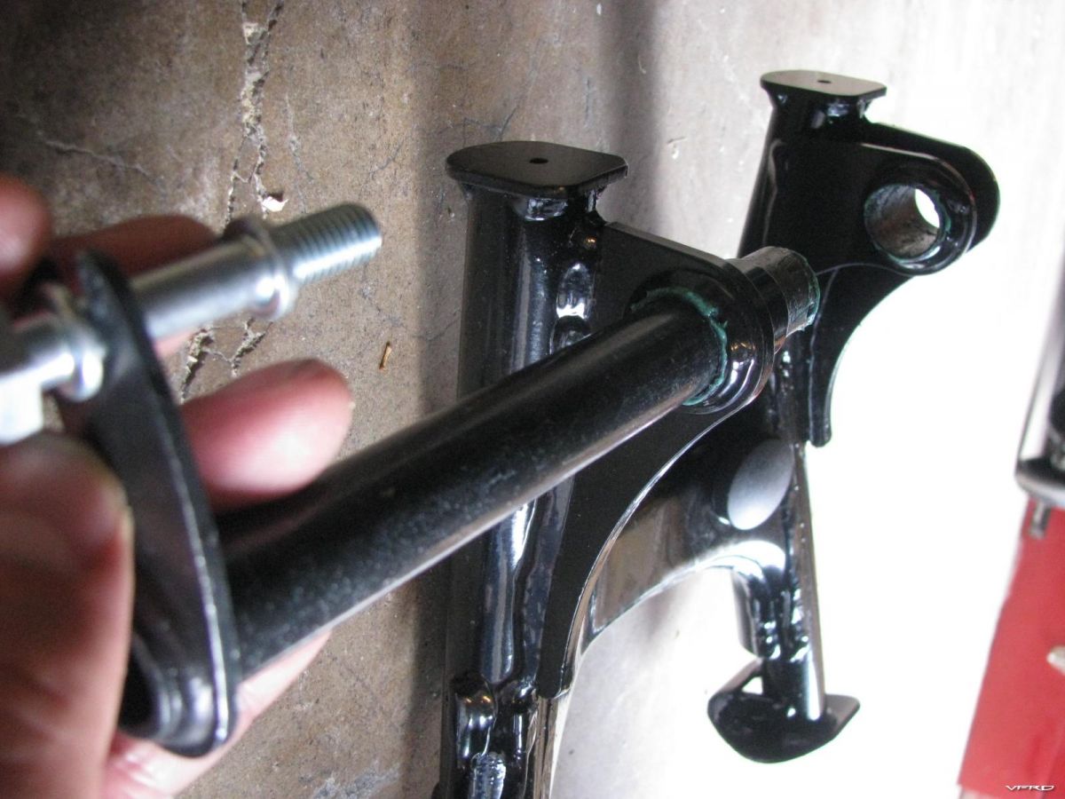
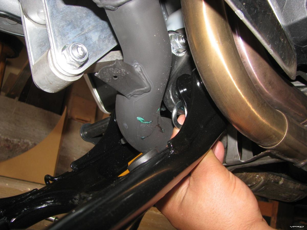
12.       Remove the fuel pump assembly and fuel level sensor assembly using a 10mm spanner or socket.

IMG_20230215_195040.thumb.jpg.4e7f29843eb5b777546242f80de78f86.jpg


IMG_20230216_180002.thumb.jpg.5be16c165ab5c578b16d015fe50db099.jpg


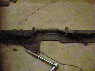
13.       Carefully remove the fuel pump assembly, it can be tricky to get out, so take it slowly.  Rock the assembly gently back and forward to loosen it. You may need to compress the metal sponge slightly, that’s ok it is just like a sponge.  Be careful not to damage the rubber surrounding the metal sponge.
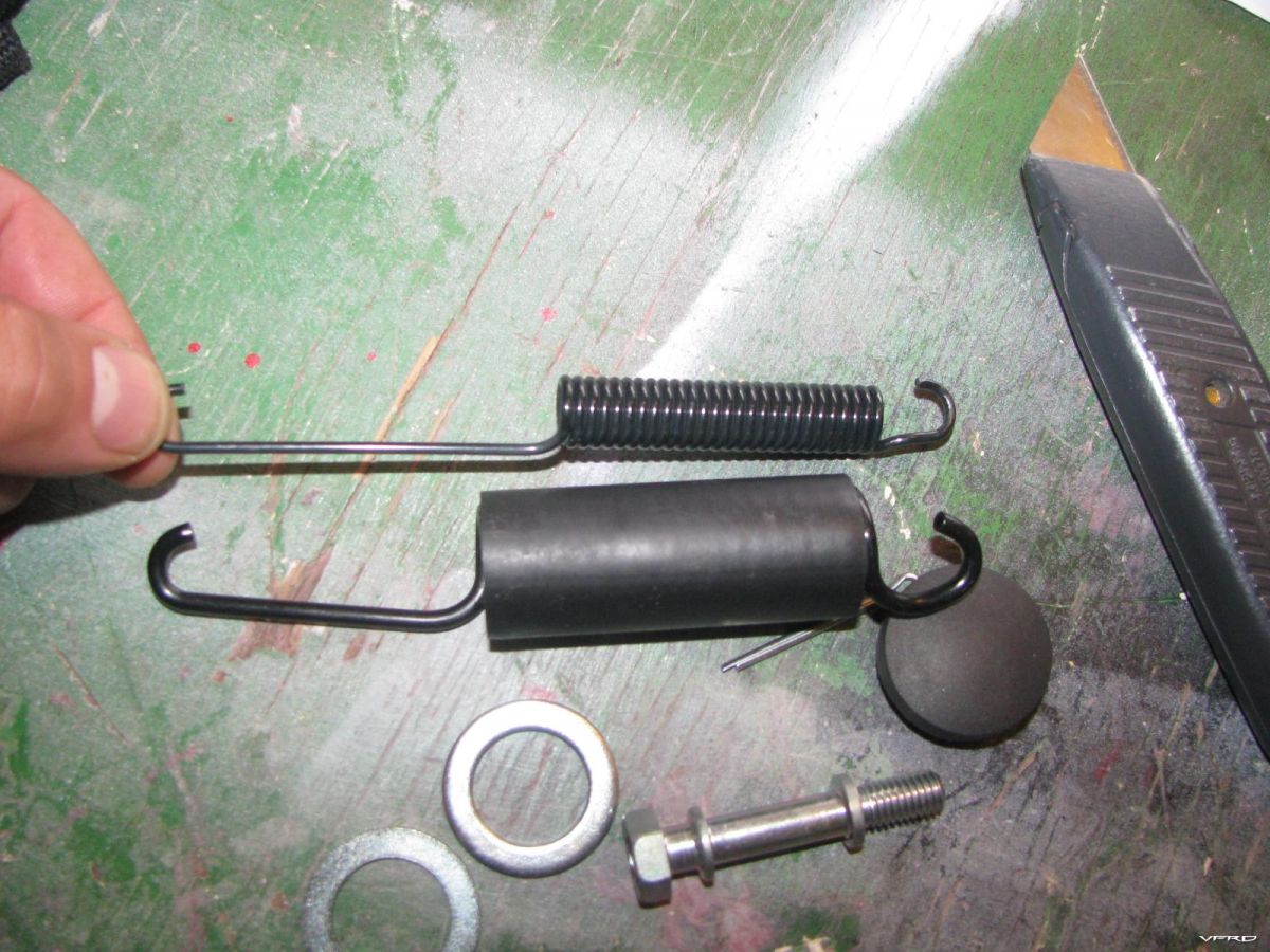
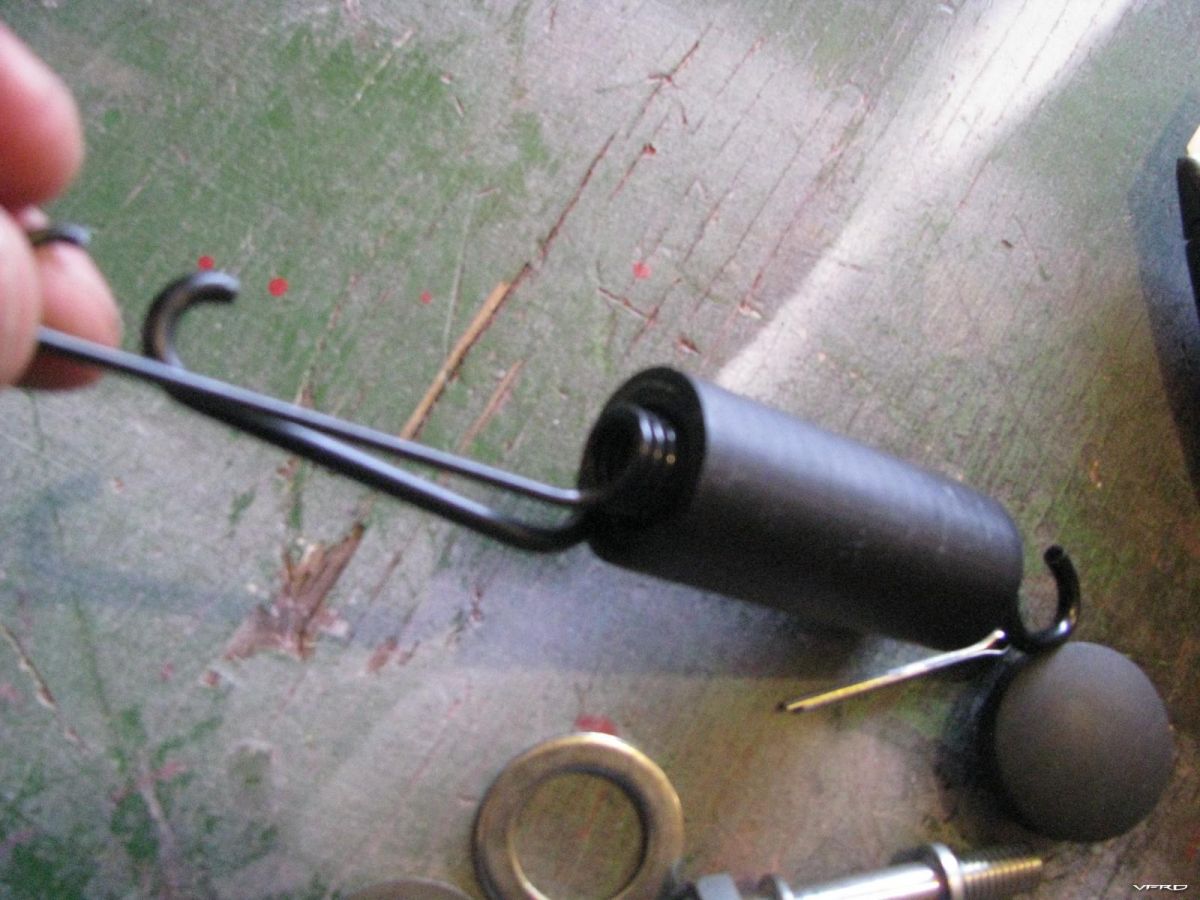
 

IMG_20230225_150108.thumb.jpg.75e0879a20053d2475d89d0764ea025c.jpg


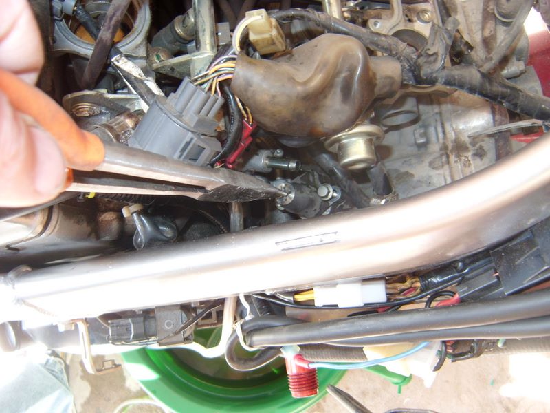
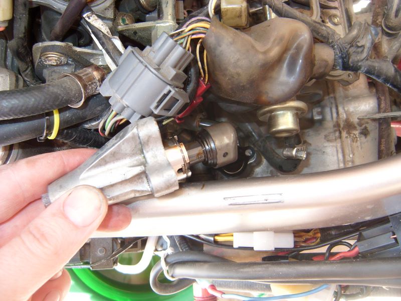
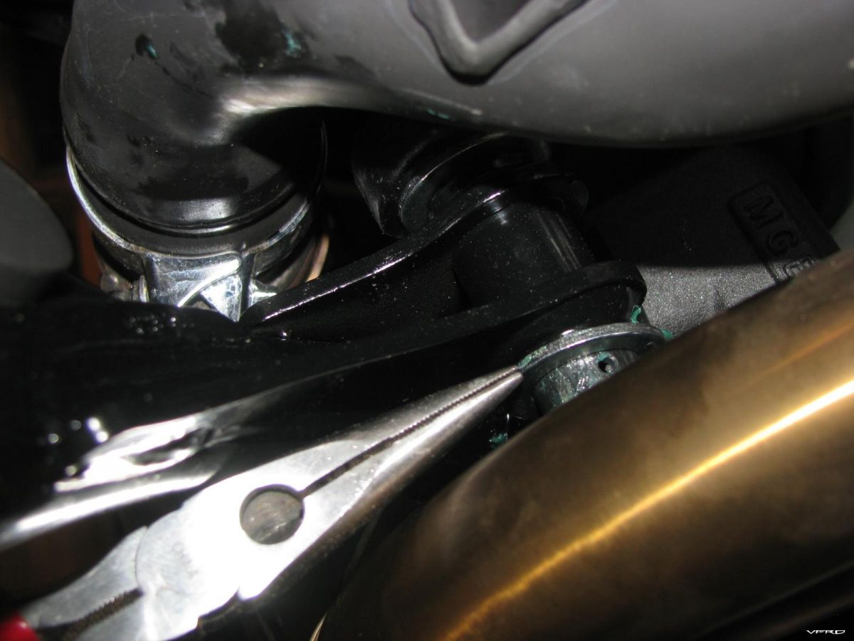
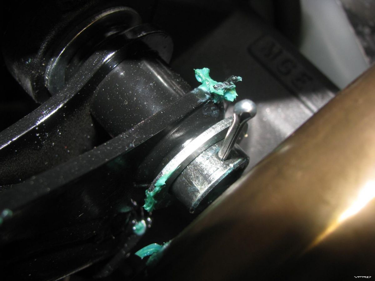
13.       Remove the fuel tank cap lock assembly.  No.26 in parts list

14.       Only 3 bolts need to be removed to get it out (see parts list)


Clean out the tank:

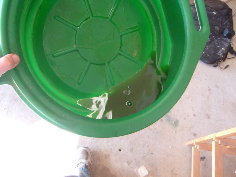
1.       Remove any fuel from tank using a siphon or syringe.  Assuming the tank is rusty/dirty, dispose of this accordingly.

2.       Rinse the tank very well with dish soap and water, then rinse out at least twice with clean water (warm is best).  This is to remove any fuel remnants.

3.       Dry straight after using the heat gun (on medium setting) or a hair dryer.  I found using my heat gun on medium heat for ~2minutes blowing into each opening of the tank to be just hot enough, but not too hot, cycling between each side of the tank and letting cool between.  Be careful not to get the tank too hot it will damage the paint.

4.       Once the tank is bone dry (this can take an hour or more), dump some screws, a piece of chain, bolts etc. anything metal will work into the tank.  This is to remove any surface rust.  Make sure you know exactly what you put in as they can get stuck.

5.       Shake the tank well with the metal pieces inside.  Do it for as long as you can.  I think I did it for around 1 hour.

6.       Remove all the metal pieces you put in and all the rust.  You can use a hoover to suck it up from the large port on the bottom of the tank.


IMG_20230216_191004.thumb.jpg.ac4d33fd32a03fcdace164a4bd23adbf.jpg


7.       Rinse the tank again with water to remove the last bits of surface rust.

8.       Fully dry the tank again immediately with the heat gun/hairdryer.


Soak tank in Vinegar (Optional):

1.       Seal the bottom of the tank with whatever you have chosen.  Tape up the 2 tubes on the bottom.

2.       Pour the vinegar into the tank from the top.

3.       Use duct tape to seal the top.

4.       Leave to soak for a few days.  Keep topped up. (I left it soak for 5 days).  If your tank is really badly rusted you can leave for a lot longer and also replace with fresh vinegar after it becomes inactive.  Once you keep the level full in the tank it will not rust any more with vinegar inside.  After 5 days the level of vinegar in my tank had not dropped at all, indicating the tank was sealed well.

5.       If the return port is clogged, now is a good time to use a long thing metal rod to unclog it.

6.       Remove the vinegar and dispose.

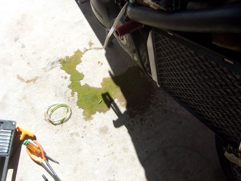
7.       Wash out the tank with some bicarbonate of soda and warm water.

8.       Rinse out well with water. I personally removed the large cover to allow quick flow of water out of the tank and ran a hose at the top for about 5mins, moving the tank back and forward.

9.       Dry immediately if not moving straight on to the next step.

IMG_20230225_161217.thumb.jpg.2045753f459c8fbf65d0d276635e282f.jpg


Degreaser:

1.       Follow the POR15 degreaser instructions or degreaser of your choice.

2.       I used the whole container of the POR15 degreaser with 1 equal container of hot water and sealed the tank.

3.       Shake the liquid well, leaving to sit for 1-2 hours on each corner of the tank.  I let it sit overnight on the bottom of the tank aswell as doing maybe 1 hour soaking on each end of the tank.

4.       Rinse the tank out well again.

5.       Dry immediately.


Metal Prep:

1.       Pour the metal prep into the tank and seal.

2.       Shake around the whole tank for at least 20 minutes, making sure all surfaces are coated.

3.       Pour the metal prep back into the bottle, it can be reused.

4.       Rinse the tank out well with warm water.

5.       Dry the tank immediately again.  This time I actually left it beside a radiator after force drying, for a few days to make sure it was bone dry.  Shake the tank around a bit while drying, as water can get trapped in crevices.

IMG_20230228_185920.thumb.jpg.75eeb4dbe653acbb98ca48c2f77fa763.jpg


Tank Sealer/Coating:

1.       Take off the lid and stir the sealer very well until it is consistent.

2.       Make sure the bottom of the tank and all bottom ports are sealed.

3.       Pour the sealer into the tank, seal the top with duct tape.

4.       Roll the sealer all around the tank.  I did this for around 30mins, allowing it to sit in each corner for a few mins also.  Make sure the tank is well coated.

5.       Let the excess drain out of the tank if possible.  For the VFR800 gen 5 tank, there is no way to do this due to the design of the tank.

6.       I used the syringe to remove any excess sealer.  You will need to do this a few times as the excess eventually flows towards the back of the tank.  You basically want an even coat on the whole tank with no pooling.

7.       Remove all port covers.

8.       Allow to dry for at least 4 days, not force dried.  I left mine for a week as you want this to be 100% dry before use.

IMG_20230313_131922.thumb.jpg.20428d4f6f886a87f10253d4aba83ce9.jpg


IMG_20230312_194444.thumb.jpg.1c953514b0ad3ae6c127b77b74e9ee1f.jpg


Reassembly:

1.       Depending on how much corrosion/debris was in the tank and whether it got into the fuel system, you may need to clean your injectors/tubing etc. or replace the fuel filters.  If this is the case you should do this before reassembling the tank.

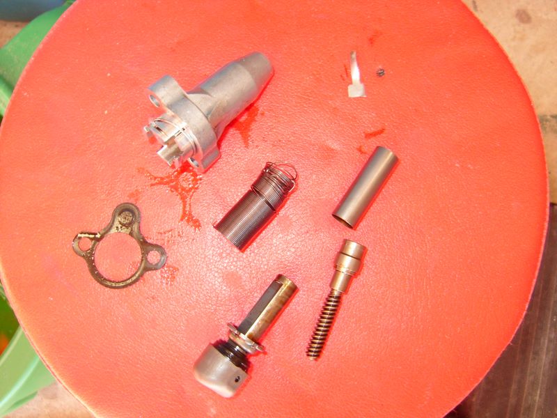
2.       If you need to install a new fuel cap, see here for removing the lock mechanism.

3.       If you need to install a new fuel filter see here.

4.       Assuming you are ready to reinstall the tank, using the new gasket and o-ring, reattach the fuel filter and fuel level sensor assemblies.  They should be torqued to 14 N.m and apply a star pattern when torquing.

FuelPumpAsemblyRetighteningPattern.jpg.95ca6307c501008e69414efdba96c113.jpg


1.       Screw back in the lock mechanism.

2.       Follow tank removal steps in reverse.

3.       Put a small bit of fuel in the tank maybe 1-2litres.  Confirm the fuel level sensor registers the fuel.  Start the engine.


The process is now complete.

Detailing a Motorcycle

$
0
0

Any Questions ?


I detail bikes plus cars, regular washing helps, with suitable techniques plus products.


We remover scratches from plexiglass, machine polish paint...plus protect.


You can use wax, or spray sealeants..


Use the brand you like or relative to the overall cost.


England/USA.


Regulator / Rectifier Upgrade (SH847)

$
0
0

The Problem:


The 5th gen VFR’s are known for having questionable Regulator Rectifiers (RR) that can suffer from overheating (other gen VFR's also suffer from the same issue).

One preventative step that can be taken is to replace the RR with a mosfet (FH020AA) or series (SH847) RR.  I went with the SH847 option as I want to run LED’s and I think this would be the best option for that.

Not all bikes suffer from overheating, however I decided to do it as a preventative step on my 5th gen.


Parts/Tools Required:


Parts List:

  • ·       Shindengen SH847 RR Kit from roadstercycle.com.  It comes with crimp and solder type connections.  Mine only came with the crimp style connectors, so I used them.  For 5th Gen VFR’s you need 12” battery cables and the default stator cables are 24” and need to be cut to length.
  • ·       4 Way Mounting bracket from roadstercycle.com (Optional)

Tools:

  • ·       Crimping tool with insulated crimping capability like:


14.thumb.jpg.3d293b1f155aac140cdaabffe82bf453.jpg


  • Soldering iron (if you decide to use the solder connections)
  • Hex tool for mounting the bracket (I can’t remember the exact size)
  • Screwdriver + Spanner (10mm) + Socket.
  • Heat gun or hairdryer
  • Electrical Tape & Cable Ties (Optional)
  • Tools required for removal of Rear Cowl


Steps:


1. Remove the Seat.

2. Remove the rear Grips


15.jpg.9762f7e363158df89935457e61ba6ae8.jpg

3. Disconnect rear turn signals and brake lights.  Turn them counter clockwise to loosen.  It can be tricky to get a good grip, so take your time.

16.jpg.73da22c4d865800bb5768daa62bb9ae4.jpg

4. Remove the rear Cowl.

17.thumb.jpg.9d6088a83b4b0b12a3295b8e5e7db593.jpg


5. Label the lights as they are left dangling (Optional).  Remember to remove when reinstalling


Lights.thumb.jpg.2e3d515916bf99b7318a8fd9a4ebbe7d.jpg


6. You can now see the old regulator Rectifier.  Remove this by removing the 2 bolts.  On my bike, 1 could be removed by the front bolt, the other had a nut that needs securing as you remove the bolt.  Access is great though so you should have no problem.  Tape up the old power connector, you wont need this.  You will be left with the following:


1.thumb.jpg.3a10347f16f250580d2bb8b48175d1d5.jpg


7. I used the 4 way mounting bracket to mount in the stock location.  You will be required to cut off one of the corners and file it smooth, like so:


2.thumb.jpg.e34efb057cf2761c03ad81ec7f94c3e3.jpg


8. Mount the bracket using the supplied hex screws.  I had to use a bolt on the rear of one of them.


3.thumb.jpg.90f48a51b109c1f7eac36f04d90e7c18.jpg


9. Mount the new RR onto the mounting bracket.  The cooling fins do not have to be parallel to the airflow for this type of RR.

4.thumb.jpg.8f584912f5eb822607f6118b1f23272f.jpg


10.  At this point you should check clearances by loosely reattaching the upper cowl.  If it does not fit, move the mounting bracket as required, or relocate to a different location.


11. Plug in the new cables.

5.thumb.jpg.18f0e4d8ab6e0eae578f5e0e4959add2.jpg


12. Cut the old stator plug.


6.thumb.jpg.bc5ee6030643d2c15cf9d4518f52c0fc.jpg


7.thumb.jpg.0285c4b080637101b76ab2d498b46e06.jpg


13. Strip a small length off each stator cable


8.thumb.jpg.ff5d8c79152ee033bcf26cce552d87b4.jpg


14. Slide the crimp connector onto one of the cables, if using the crimp style connectors.  Otherwise use the solder type connectors.


9.thumb.jpg.266c5c7abdfca1ad1436597a1abc4038.jpg


15. Crimp between the midpoint and the end point.

16. Strip a small length off the new stator wires.  They will need to be cut to length first.  I left a little spare, just in case.


10.thumb.jpg.3d796469d3bfcdfa54dfdf2d4f0396a5.jpg


17. Slide this into the other end of the crimp connector and crimp between the midpoint and end point.

18. Do this for all 3 stator cables

11.thumb.jpg.92e0addf184cdff9b5ed02d300eb9a14.jpg


19. Test by starting the bike and checking voltages, it should be 13V’s at idle and over 14V @ 5k rpm.  If all is ok, continue.

20. Use the heat gun or hairdryer to heat the heat shrink around the crimp connectors.  Use tape around them (Optional).


12.thumb.jpg.3a5dd3a4732e2f75df03cab3dbef6a86.jpg


21. Cable tie the cables out of the way (optional)

13.thumb.jpg.5b688f33e4475cca216a7e5e9207d9d8.jpg


22. Reinstall the upper Cowl in reverse order.


Bag of Goodies

$
0
0

Bag of goodies showed up on my doorstep today.

----- What do you think @bmart ..?? 

20230427_151710-M.jpg


Clean up rusty pitted forks - sort of...

$
0
0

Hello everyone, 


This is is a quick how-to for those with crappy rusted forks. It's not a cure-all but might help reduce the amount of pitting and help your seals last a bit longer. The only ways to ultimately tackle rusty forks is to re-chrome or replace. This is just a temporary fix and doesn't work on heavy corrosion 


You will need: 


1. Cola (any brand as long as it has Phosphoric acid in the ingredients)

2. Piece of aluminium foil

3. Protective oil of your choice (I use ACF50)


Method is very simple: splash some cola on the forks and swish it about so it gets into the rust. Apply some cola on to foil sheet also. Now rub the soaked foil across the rust until it is completely removed.  


You can actually feel the rust reducing as you rub. Go gently to avoid scratching the chrome - it works just as well gently. Best to rub left-to-right as this will create microscopic ridges for fork oil to dwell and protect the fork (same principal as honing a cylinder for piston rings). Up and down would create microscopic tears in the seal's mating surface, shortening its life. 


In reality it it doesn't really matter  which way you rub - just go gently. 


When you're satisfied simply wipe off the cola and apply some sort of lube protectant. 


Lots of rumours on the internet suggest the phosphoric acid "converts" rust and the tinfoil chemically fuses bits of itself to the pitted area. I'm not a chemist and cannot confirm-or-deny this but I feel there is not enough Phosphoric acid in cola for this. 


My my gut feeling is that the tin is harder than rust but softer than chrome. It removes the former without harming the latter. But the acid and chemistry might help things along. It creates a grey residue which might suggest the acid is working. 


The only thing I know for sure is it works well. 


You can can see from the pics how much of an improvement there was, although some deeper pits remain, although  they are much smoother and kinder to the seals.  


One old-timer told me he seals the pits with flexible superglue and builds them up to match the surrounding surfaces. Normal superglue it too brittle. Sounds like a good idea but really time consuming. 


This is process took less than 5 minutes and cost less than half a pound. 


Hope it helps someone out. 


Best, 


stray


IMG_4177.JPG

IMG_4296.JPG

IMG_4297.JPG

IMG_4298.JPG

IMG_4299.JPG

Rear Axle and bearing Inspection

$
0
0

I decided to check out the rear axle since my bike has 23k on it, to check for signs of bearing failure and axle wear.

Begin by losening the main bolt

axle02.jpg

The main bolt is a huge 46mm jobbie that is on very tight I borrowed Craigs socket to get it off, at this point you just want to get it loose, since its easiest to do with the wheel on the ground first loosen this bolt with the wheel down on the sidestand.

Remove the rear wheel

axle01.jpg

Remove the Chain Gaurd

axle05.jpg

It is held in place by 2 screw type plastic clips, 2 hex bolts, and 2 brackets that hold the brake hoses.

axle03.jpg

Once you get the chain gaurd off carfull not to lose the retaining backers that hold the hose brakets

axle06.jpg

Remove the lower air gaurd

axle07.jpg

Remove the main bolt and the washer, then loosen the pinch bolt on the top rear of the swingarm, then use the spanner from the tool kit to get enough slack in the chain to unhook it from the sprocket.

axle08.jpg

Remove the rear hub

axle10.jpg

Inspect the hub for rough bearings, if it turns notchy, noisy, or fits loosely then it should be replaced, put some grease on it anyhow. There is a spacer inside that you could mistake for a bearing, its just a spacer and it fits in there loosely.

Remove the rear brake

axle11.jpg

axle12.jpg

Inspect the axle for scoring

axle13.jpg

If you have a dial indicator and a v block check it for runout as well, check for damage, replace if nessisary, if not grease that puppy up , then inspect the needle bearings, if they are good repack them with grease.

axle14.jpg

axle16.jpg

My bearings all turned smooth and easy, they were all tight, and the needle bearings had grease, I just packed in a bit more, nothing bad to report, the axle was in good shape, I cleaned up my hub and switched the sprocket around. I also cleaned off the grime from the chain guide, since you have access to it now is the time to clean it!

What is suppose to be the SAE equivalent to the 46mm, it is 1-13/16 in. and is available at OSH for $19.95. I have not tried it yet to see if it will work though. 46mm equates to 1.811018 in. while 1-13/16 in. equates to 1.8125 in. - ULEWZ

Bearings - front wheel replacement

$
0
0

Replace bad wheel bearings I have been getting my bike ready for riding season, I had a warped front brake disk and it tore up one of my wheel bearings from all the rattling when I used the brakes. I don't know if the disk warped first or the other way around. I just had a day of bike maintenance today, new chain, new tires, new bearings, new front disk, new pads.

Here is my new disk, see how poor of shape the oil seal is.

bearings01.jpg

You can tell your bearings are bad if you can move them back and forth or in or out, they should spin but not float around inside there.

Remove the brake disks 6mm hex 6 bolts.

bearings02.jpg

I pried out the oil seals with a large flat screwdriver, then pushed a rod thru the inside and made contact with the outer bearing and hammered it out. You have to move the rod around so you don't get the bearing twisted up.

bearings03.jpg

They were in bad shape that spacer needs to go back in, cleaned it up and greased it.

bearings04.jpg

It was rusty in there, I cleaned it up with some steel wool and greased it up.

bearings05.jpg

The new set $46 whew, I gotta find a cheaper source.

bearings06.jpg

My bearing hammer heads, I use the threaded rod to compress the bearings into the slot first.

bearings08.jpg

Make sure the bearing hammer is big enough to catch the outsides but not too big it wont fit.

bearings09.jpg

Compress

bearings10.jpg

The hammers have a handle on them you can attach and then bang the bearings in the rest of the way. I don't hammer them in right off the bat to keep them in strait and not damage them.

bearings11.jpg

Put in the spacer and do the other side.

Petcock rebuild

$
0
0

My 1990 VFR750 petcock was leaking. In my case, leaking from both the petcock body as well as through the outlet when the petcock was turned off. After reading a bunch on the forums I learned that it can be rebuilt. Some threads that were helpful:

https://www.vfrdiscussion.com/index.php?/forums/topic/87331-petcock-body-leaks/

https://www.vfrdiscussion.com/index.php?/forums/topic/82877-3rd-gen-fuel-petcock-o-ring/


Should have got the kit from NRP but I decided to homebrew it.

I thought I could add to the discussion here by providing details.

I recommend the following Viton o-rings.


Petcock to fuel tank: 24mm ID x 2mm wide, quantity one (not sure if still available as OEM? Disappeared from Honda p/n’s on revzilla, partzilla etc. but I found the size on one of the forums)

Side plate to petcock body: 29mm ID x 1.5mm wide, quantity one

Internal seal: 7mm ID x 1.5mm wide, quantity one (two if you are fastidious) (FYI I used 7mm ID x 2mm W and it was a little big, I’d recommend go down to 1.5mm W)

Shaft seal: 7mm ID x 2mm wide, quantity two

*If turning your petcock “off” doesn’t stop the fuel flow to the outlet after you rebuild, you’ll also need a new spring about 0.9 wire thickness x 9.5mm OD x 10mm L. You might have to try different springs depending on how firm or soft the new spring is, but this is what worked for me. I got it from this kit:

 https://www.amazon.com/Compression-Assortment-Stainless-Different-Individual/dp/B0BL7RYQ27/ref=sr_1_4?qid=1707004725&th=1


So that’s the short version! If you want pics and step by step keep reading!

Sprockets

$
0
0

Afternoon guys, I was going through the chain and sprockets on the 1999 and I was wondering if you guys may know the answer to my questions

I was wondering if you think this front sprocket is a Honda part . I see that it has the rubber on it to help with noise and has the correct ( stock ) number of teeth but I do not see any Honda markings, the rubber ring looks like it has depressions around the edge, my guess is from the chain. What is the best way to know if it is worn out?, the back one sits fine on the chain with no air gap between chain and rear sprocket.


IMG_5934.JPG

IMG_5935.JPG

Cam Chain Tensioner, Without Throttle Body Removal

$
0
0

Ok, I am not a writer. I don't have the witty banter abilities of great technical writers who pull you into their project no matter the subject. Instead I am a typical desk jockey who rides VFR and fixes stuff if he can. Before I get into the "easy" way to change the CCT, let me point out that I did not come up with the process on my own. I borrowed bits and pieces from lots of people. The best replacement guide can be found here, CCT change by Rad, where it is done "by the book". In the resulting discussion it was revealed that removing the Throttle Bodies and so forth was a waste of time, as the CCT can be removed without it.

As a second note, I did not change the rear CCT, and I don't imagine I know or could discover any easier way...it seems simple enough already. See the link above to find how to change that CCT if needed.

As a third note (I like notes), I don't believe the CCTs EVER go bad...I think they make noise when the spring loses a bit of tension...more to come on that later (see how I "hook" you...just like the creative writing class said!)

So on to CCT removal and replacement (this order works best I have found)...Anyway, I didn't have music playing, I don't drink beer, and I barely remembered to take pictures....so bear with me. Finding the CCT was the first chore. It is located on the right side, kinda behind and back of the R/R. To find it you need to remove:

Right Fairing

  • 8 allen screws
  • 1 blind rivet
  • Slider (if applicable)

Seat

  • Just use the key, and remove

Tank

  • two 8mm head bolts, use 1/4" driver
  • Restraint Cable
  • Two 10mm head bolts at back of tank

Air Box Top

  • Hose from top
  • screws around perimeter

Air Box Bottom

  • Velocity Stacks, Phillips Head Bolts
  • Sensor connector on bottom
  • Vacuum line going in front of box
  • Small connections at the back

When moved, the airbox looks like this:

airbox_moved.jpg

Note the airbox was just rotated away from the CCT. Tank was also rotated the same way and laid across the seat rails. You can see the CCT at the very bottom, just right of center.

Now you are almost there....just need to remove those cooling hoses to make it stupidly easy to reach the CCT. Remove the one pointing out first, and connect a short section(2-3 feet) of 1/4" or similar hose (I didn't measure it, just some I had around, but 1/4" should be about right).

drain_tube_2.jpg

Route this into a drain pan or later you get this:

opps__piddled.jpg

next remove the second hose....this is what makes the first connection take a bit of a leak

second_hose_removed.jpg

not much fluid is lost...a bit more than is pictured here:

antifreeze_from_cct_change.jpg

Don't leave this for the dog/cats to drink, unless you don't like them much....

Now it's time to remove that CCT! Simply use your 8mm socket on extension, and take the center bolt out:

removing_the_cap.jpg

This is where the "key" goes in.

insert_lock.jpg

The keys job is to stop the CCT from extending when you remove it from the engine. Keeping it from extending makes it less likely that you knock a bit off into the motor, and also makes it easier for the CCT to clear the various bits above it. If you are really ambitious you could actually rotate the CCT to shorten it and make it even easier...but that would be over kill. After loosing both mounting bolts, and removing them, the CCT just slides right out:

cct_coming_out.jpg

Here is where I have to admit I have a problem. I enjoy seeing how things work. I managed to restrain myself from taking apart my new CCT to see how it works, but the old one was just there....so I had to do it. Initially I planned to try the Reddog idea of tightening the spring....but I screwed up my spring after I removed it, so that was nixxed. Here is a nice picture of my CCT doing it's best Humpty Dumpty impression:

cct_falling_to_pieces.jpg

you can see where the spring is messed up....yours won't look like that (don't take it apart to see tho). Let me describe the parts, so hopefully this makes more sense to those who want to know. Those who don't want to know can skip to anther thread or something...

Clockwise starting from the left you have:

  • CCT Gasket
  • CCT body, with circlip just slid back
  • key
  • Sping(in the middle)
  • bushing/sleeve
  • Worm Drive
  • Shaft with puck on end

The sleeve/bushing goes around the worm drive, and over the shaft below the locking tab. The locking tab doesn't come off the shaft (without removing far too much).

The way the CCT works is this:

The spring is coiled around the shaft, with one end going into the slot at the bottom of the worm drive, and the other end into a slit at the top of the CCT body. As the worm drive is rotated clockwise, the spring winds up....and if allowed the worm drive will rotate counter clockwise to release tension. The worm drive can only rotate 4 times before the Shaft reaches its stopper. I believe the reason you begin to hear CCT noise is that the spring is able to unwind with a bit of Cam Chain stretch, and thus the spring is not as tight as it was originally. This loosness allows a bit more play that normal, and oscillations begin. Whether different oils help or not I don't even want to discuss.

If you wish to attempt to modify your CCT to save some cash, here is how you do it:

Holding the CCT in such a way that your finger restrains the shaft from advancing, remove the "key". Using a small (probably modified for the purpose) screwdriver, rotate the wormdrive from the access hole clockwise until it stops. Counts the revolutions. It will stop with the shaft all the way compressed. Now reinsert the key, and while still holding the shaft, slide the circlip down so it no longer restrains the locking tab. slide the locking tab carefully up the shaft out of the grooves, noting 2 grooves are wider than the other 2. Then very carefully rotate the shaft counter-clockwise 1-2 times as many revolutions as it took to compress it initially. (this figure is a guess, your results may very, I make no guarantees..written, expressed or otherwise, not available in all locations, subject to rule changes etc). After rotating the shaft counter-clockwise, slide the locking tab back down, and replace the circlip. Re-insert the screwdriver and rotate the gear clockwise to compress the shaft once more. Now you can reinstall the CCT and see if you saved $100.

Reinstalling the CCT is the reverse of removal (I hate it when manuals state that, but it's true. Just check and make sure all connections are replaced or you may not like the results...I didn't.

look_close.jpg

That is the connector I forgot. The FI light was blinking when I started the bike. I was able to get it back on without removing the air box again using a long thing screwdriver. Speaking of which, here are all the tools I needed to do the job:

every_tool_needed.jpg

1/4" driver handle

1/4" Rachet

1/4" x3" extension

1/4" x 6" extension

1/4"x1/4" socket for hose clamp

1/4"x8mm socket for CCT bolts and tank bolts

Phillips Screw Driver

3/8" Rachet

3/8"x10mm socket

3/8" x 6" extension

Needed this time, but not always required:

Long Needle Nose pliars

Extra Long thin screwdriver

Telescoping Magnetic pickup tool

Some pictures were not included, you can see them all here:

http://www.wiremybike.com/Slideshows/CCT%20Change/

Check your rear axle nut!

$
0
0

In the process of installing a new chain & sprockets. Discovered that mine is loose. It hasn't moved past the stake, but it was only a matter of time. Don't want that assembly coming apart! Need to put this on the gas stop checklist.


TOOL needed 1992 750F- Adjusting valves

$
0
0

Hello


Does any one have the part number for the tool that compresses the valve spring from the top of the motor to allow changing the shims? Pulling the cams out doesn't sound like the thing I want to do


I called Motion Pro to get the tool and got an lazy incompetent fool instead of help.

thanks


H2


What gaskets, etc, should I have for the valve clearance service?

$
0
0

Just wondering if anyone could provide a list of the gaskets I should pre-order for my first valve clearance check on a 2009 VFR800. According to the schematics there's a lot that can be replaced, but are they all necessary? Thanks, Glenn

VFR1200F Service Video Guide

Viewing all 78 articles
Browse latest View live