Good write up on proper break in for new motors myths and facts.
https://thumpertalk.com/articles/engine-break-in-truth-lies-and-what-you-really-need-to-know-r707/
Good write up on proper break in for new motors myths and facts.
https://thumpertalk.com/articles/engine-break-in-truth-lies-and-what-you-really-need-to-know-r707/
Hello All,
A quick guide on how I refreshed a K&N air filter on the 5th Gen. This is not the only way to do it and may not even be the right way - it's the way I did it and it came out great.
First you have to remove the tank and the air box cover. No pics of that but the front left screw on the air box was a b@stard. It's also usually the most rusted (exposed to salt spray) and most likely to strip, so go easy.
I bought new stainless screws m5 x 20mm x 7 units panhead, if anyone is interested.
Thats when you get the first look at your air filter. Mine looked like it had been there since the Ark touched dry land but I was pleasantly surprised to find it was K&N. I know many members don't rate these very highly and personally I wouldn't have installed it but this is a budget machine and rechargeable filters fit the bill.
It it was loaded with crud and insects. Some of these bits had combined to form solid big chunks. Nasty!

I also removed the velocity stacks and bottom air box housing to do a valve check (in another thread). They have markings on them showing orientation for reassembly. 
The stacks are held in by blind shoulder bolts one of which had to be drilled out. Used an old Travis Perkins bolt extractor to get it done. 

Having completely removed the air box I now turned to cleaning the air filter.
First job was to turn it over and gently tap the edge so the loose bits could fall out. Then I ran a vaccum cleaner over each please to suck out whatever I could. Make sure you vacuum the top of the filter to lift dirt out the way it went in. Vacuuming the bottom gets dirt trapped in deeper. The amount of debris removed through these methods truly surprised me.
Most of the grit was ingrained so I decided to wash the filter in warm water with liquid laundry detergent. Yes, laundry detergent. The filter media is a cotton gauze and can be washed with the same stuff as your cotton under-crackers.
Liquid is is better than powder detergent because the latter sometimes gets stuck in the fibres whereas the former is completely dissolved and washes out.
I let it soak in a strong solution for a couple hours, throwing some dishwash soap in to dissolve the greasier bits.
This is the cr@p that washed off easy.

This is what floated to the surface during the soak. Best way to get rid of it is to overflow the bucket and the crud spill out over the top. Otherwise you lift the filter out of the bucket right through the dirt you just removed, thereby reinserting it. 
This is what sank to the bottom of the bucket and looked like dense, dirty beach sand.

Then the filter was hosed off in the shower (don't tell the missus) and immersed in a fresh bucket of soapy water. I got a soft long-bristle nylon brush and set to working it along each pleat with soap, gradually loosening more crud.
Between the gentle brushing and tapping this is what came out.

The other filter belongs to my other bike. Thought I'd do them both at once.
With the oil and dirt removed the filter took on a dull grey appearance. I was pleased with how clean it came out and inspected it closely for any hidden trapped dirt. There was none so it was left to dry overnight.
The next day I applied genuine K&N oil pleat by pleat using their squeezy bottle applicator. Some say it is just normal ATF, and they might be right, but I'm not clever enough to know for sure and it wasn't exactly expensive so I used the real deal.
This pic shows the difference between oiled pleats and dry grey pleats.

When the first side was done I flipped it over and started again. Note how I am halfway through on the second side and you can see some oil from underneath seeping through. Some say if you leave it 15 minutes it will soak throughout but I thought it was still a bit too dry so applied oil on both sides. 
The final pic shows filter fully oiled. It still had some dull spots but those got redder after a while when the oil wicked through.
Hope this helps people doing the same thing out. I'm no expert but believe any rechargeable filter could be done the same way. Just remember that dirt is removed the same direction it went in otherwise you're driving it further into the fibres.
Stray


QuoteK&N has discovered that in certain KN-204 oil filters manufactured between March 1, 2016 and September 30, 2016, oil can leak at the area where a nut (intended for use to remove the oil filter during routine oil changes) was welded to the bottom of the filter canister. If there is such a leak, oil could come into contact with the rear tire or rear brake of the motorcycle on which the filter was installed. If this were to occur, it could lead to a loss of control or a crash. Therefore, K&N is offering to replace the affected oil filters at no charge. This offer of a free replacement also applies to those covered KN-204 oil filters that were purchased for use in an application other than a motorcycle, such as an ATV or PWC (personal watercraft).
Might have a problem.
Before we use any power tools, let's take a moment to talk about shop safety. Be sure to read, understand, and follow all the safety rules that come with your power tools. Knowing how to use your power tools properly will greatly reduce the risk of personal injury. And remember this: there is no more important safety rule than to wear these — safety glasses.
Always wanted to say that! (credit Norm Abram)
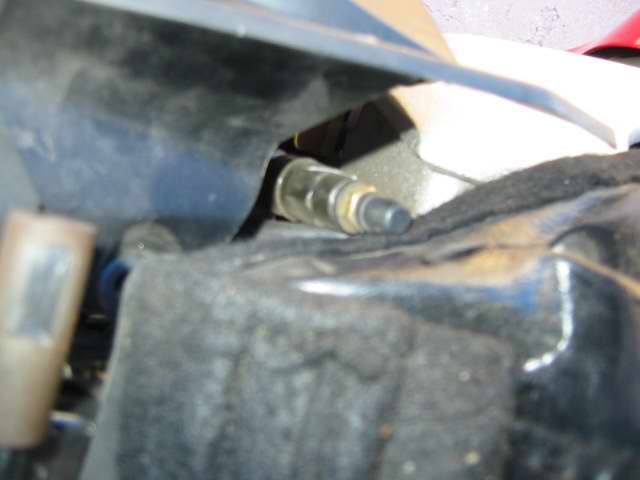
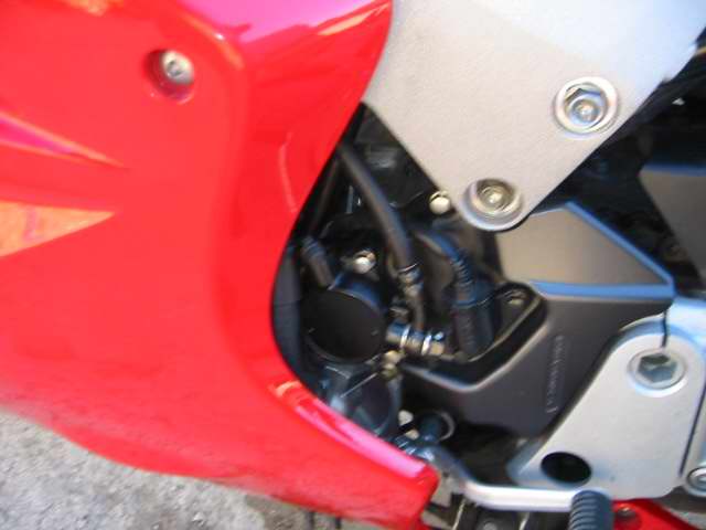
Below are some pictures of the stator to regulator/rectifier 3P connector located on the right had side of the bike under the fairing. This is what lead me to a stator replacement (besides the not-so-cool smell of burning plastic and flat batteries)...

Totally melted white connector block.
References:
Besides your regular tools you will need:
As far as level of difficulty goes this job rates just slightly harder than changing your oil - and only because a couple more tools are required.
First, remove both left and right side panels then remove the radiator overflow bottle and hang it out of the way (no need to empty it).

Radiator overflow - wired out of the way
Next, undo the electrical connectors. I had a heck of a time trying to figure out how to get the sealed type connectors opened. There is only ONE tab (despite what I thought) and they can be a little troublesome to pull apart since the seals create a bit of suction.
Here is the one tab you need to lift up on (arrow)...

Sealed Connectors
TRICK - You will also need to disconnect the stator to regulator/rectifier 3P connector on the right hand side. Once it is disconnect tape a string or wire securely to the end. This way when you pull the stator off the left side to the bike the string/wire will follow --- this will help you to pull the new stator wire back through the engine "V" later.

Stator plug taped to wire - prior to pulling
With all the connector undone you can get to work on the left side case cover. You'll want to put a rag down to catch any oil that spills out - I only lost about 1/4 cup and my engine oil level was still good at the end to this repair. With the bolts removed carefully pry the left side cover off. The magnets in the flywheel want to hold the cover on as does the gasket. I managed to find a couple of tabs that I could get the screwdriver behind and pry on - just go slowly and work the cover evenly off the aligning dowels. You shouldn't have any problems.
With the cover removed my stator looked like this...

Toasty stator
In comparison the new stator looks like this...

Old stator (left) and new stator
Remove the old stator, clean the old gasket material off the cover, replace the stator and torque to specs.
TIP - Placing the rubber wire grommet into the cover was a bit of a stretch no matter how I tried. For a while I thought that the grommet was in the wrong place and too close to the stator. In the end I just worked the grommet into place as I tightened down the wire keeper and then tightend down the stator.
If you are replacing the flywheel - read on.
Remove the single bolt holding the flywheel in place. To do this you will need something to stop the flywheel from turning (engine compression won't do it). I used a cheap strap wrench.

Cheap flywheel wrench
Next, Honda specifies a flywheel puller in the Service Manual. It is nothing more than a correctly threaded bolt with arms that can be hammered on. The "bolt" threads into the end of the flywheel and presses against the end of the tapered shaft that the flywheel sits on. Hammering on the "bolt's arms" caused the bolt to push against the shaft and force the flywheel off the shaft.

Flywheel Puller
TIP - Bring your new flywheel into a machine shop and have your own "puller" built.
TRICK - Service Honda lists the tool as a "PULLER DYNAMO" and sells it for $16.46 USD. My rental puller cost me $10 so it's probably worth the extra $6.50 to have the correct tool for the job - you can alway rent it out to your VFR buddies for a case of beer and you'll end up way ahead!!

Flywheel with rented puller.jpg
Here is a close-up. If you do use this method you will need a puller that can fit through the center of the flywheel and push against the end of the tapered shaft. The end on this puller was about 5/8" and fit through nicely without going inside the tapered shaft or damaging the threads on the flywheel (my flywheel will be replaced with the kit anyway but no sense doing a bunch of damage). Those holes in the flywheel are also quite small so you'll want very small arms on the puller. I had to place each arm into their respective holes and then reattach them to the body of the puller.

Flywheel with rented puller close-up.jpg
When you have the flywheel removed clean off any stuck on gasket being careful not to let any get into the engine. It should look like this...

Leftside crankcase empty.jpg
Apply a thin film of oil to the tapered shaft then slide the new flywheel on and torque it into place using the flywheel wrench to keep it from spinning. There is no shear pin or key - it's just a friction fit.

Cheap flywheel wrench
Now apply sealant to the specified locations (I gave a thin coat all the way around), place the gasket on the dowel pins, more sealant, then replace the cover with the new stator installed and torque to specs - tightening in a criss cross pattern.
TIP - In this case the specs on the bolts aren't published in Chapter 17 of the Honda Service Manual. Instead look in Chapter 1 - General Information page 1-12 to find the "Standard Torque Values".
TRICK - I read that someone cracked their cover by using the bolts to pull it into place. This is because the magnets in the flywheel want to pull everything out of alignment and the cover was not properly seated on the dowel pins. I used some rod to help align the stator cover. An even better solution would be to buy a couple of bolts about 2-4 inches longer than the cover bolts. Take those extra long bolts and cut the heads off and you'll have some aligning studs. Thread the studs in, place the cover on the studs and then slide the cover into place. Remove the aligning studs a "Bobs your Uncle".

Rods to help guide case cover while installing
Once everything is torqued in place, pull your new stator wire back through the engine "V" using your string/wire (you may need to fiddle a bit with it). Then reconnect all the electrical plugs - might as well add some dielectric grease to them while your at it.
Replace the radiator overflow bottle and reattach your fairings. Check your oil and start her up.
To get the full benefit of your the new alternator you should really upgrade the remainder of the charging system --- check out Electrical Upgrade - How To With Pics.
The last thing I added was a voltmeter to monitor the situation. You can see it here at Lascar Voltmeter Install Pics.
NOTE - most of the tips and tricks came from this website in various posts and references. Thanks for all your help.
This guide was created because I couldn't seem to find one that was very thorough and included pictures of all procedures. This guide requires the use of Speed Bleeders as it makes life so much easier! You can follow this guide using the old school method as well, but it will require more time and patience.
Readers Notes:
Left and ride side are determined as if you were sitting on the motorcycle.
Images come after descriptions.
Initialisms:
LBS: Linked Braking System
LPCV: Left-side (Servo) Proportional Control Valve (Battery side)
RPCV: Right-side (Rear) Proportional Control valve (Opposite battery side)
LMC: Lever Master Cylinder (Front)
RMC: Rear Master Cylinder (Pedal)
SMC: Secondary Master Cylinder (Left-Front Caliper)
FSM: Factory Service Manual
Parts Required:
One man bleeder kit (optional)
Speed Bleeders Part Numbers:
Front right caliper SB8125
Front left caliper outer bleeder SB8125
Front left caliper inner/centre bleeder SB8125
Rear caliper outer bleeder SB8125
Rear caliper inner/centre bleeder SB8125L
Clutch bleeder SB8125L
LPCV SB8125LL
RPCV SB8125
Part 1: Theory
Part 2: Diassembly And Prep
Part 3: Procedure
Part 4: Assembly
Part 5: Clutch
Part 1: Theory
The LBS is confusing for some when it comes to understanding how it works. The function of the sytem changed from 5th generation LBS to 6th generation LBS. I'm not too sure what the changes were, but I do know they operate differently. The way the 6th generation LBS works is; when the front lever is applied, only five out of the six (three pistons in each left/right caliper) caliper pistons actuate as well as the centre piston in the rear caliper leaving the left caliper centre piston untouched.
When the rear pedal lever is applied; only two out of the three rear caliper pistons actuate as well as the left front caliper centre piston. The LBS only works when the motorcycle is moving however, you can test this by propping your bike on the centre stand, rotating the rear wheel and applying the front brake; the rear wheel will not stop spinning.
The way it works is by force. The SMC is mounted above the left caliper that's attached to the fork and with the motorcycle moving, the rider will apply the front brake which squeezes the pads on the rotor and that drag pivots the left front caliper up which actuates the SMC and brake fluid gets pushed through to the LPCV and then to the rear caliper centre piston. The rear doesn't work in the same way because there's actually a brake line that goes all the way to the front left caliper that actuates that one centre piston by it's lonesome with the application of the rear pedal.


Thanks to BartmanEH for the above picture!
Part 2: Disassembly And Preparation
You want your bike to be on a level ground and prop the bike up on it's centre stand for this whole procedure. Rotate the handle bar all the way to the left so the LMC is level. Remove both screws and remove all the old fluid inside the LMC. You can use a turkey baster or rags, whatever you wish. Once the old fluid is out, fill it up with fresh new fluid. Make sure you squeeze the front lever a few times just incase you got any air bubbles when removing the old fluid.

Using an allen wrench, loosen, but do not remove the left front caliper bolts.

Remove the seat and do the same procedure you did for the LMC to the RMC. Don't forget to press the pedal lever a few times to remove any air bubbles.
Remove the rear wheel.
Remove the two bolts that hold the rear caliper together. The inside one is tricky and I needed to use a long 12mm socket to reach it. Once the rear caliper is removed, mount it at the 10 o'clock position on the rotor. The reason for this is so the inner/centre bleed screw is facing up, not parallel to the ground.


Part 3: Procedure
The procedure and order we're going to follow is the same one listed in the FSM, but with more pictures and explanations. Sections C. and D. are the most difficult. You will need a helper as well.
USING FRONT MASTER CYLINDER LEVER FOR A. AND B.
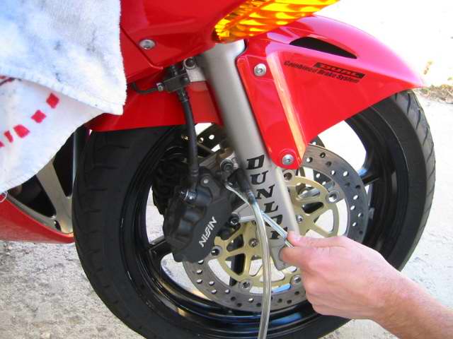
A. Left Front Caliper, Upper/Outer Bleed Screw

This is basic bleed. Open very slightly, usually about a 1/4 turn and pump the front lever until new fluid comes out. Even though I use speed bleeders, I still pressurize it old school method just to be on the safe side. The old school method is; with the bleeder screw closed, have your helper pump the front lever five times and hold. While holding, gently unscrew the bleeder screw until fluid comes out and before the lever reaches it's maximum travel, tighten the bleed screw. Top up the fluid level.

B. Right Front Caliper, Single Bleed Screw
This procedure is the same as above. Make sure you keep an eye on the fluid level as it drains.
USING REAR MASTER CYLINDER PEDAL FOR C. TO G.
C. Leftside PCV (Battery side), Single Bleed Screw Actuated via SMC

This step is the most confusing and difficult one as it requires good timing between yourself and your helper. The SMC is not attached at all to the front lever in anyway. You can unscrew the LPCV bleeder screw and pump the front lever all day long and no fluid will get pushed through. You could manually actuate the SMC by hand and only a little bit of fluid will come out and then stop. The correct method to do this; from what I've gathered on how the system operates and without using a vacuum bleed tool is as follows.
Remove the two bolts that hold the left front caliper on. I used an aluminum L-bracket I had lying around to wedge between the pads so they don't close.

Tilt the caliper 15° from the ground so the inner/centre bleed screw is facing up.

Your helper will be on the RMC side pressing the pedal and you will be at the left front caliper in charge of manually actuating the SMC and loosening/tighten the LPCV bleed screw. The way this system works is; there's a brake line that goes from the RMC to the SMC and from the SMC to the LPCV. Because there's no reservoir at the SMC, there's no way for new fluid to replenish to continue being pushed through the lines and out the LPCV bleeder screw, however, this is where the RMC comes in.
When your helper presses the RMC pedal down, the SMC piston will get pushed out filling it with fresh fluid. Once your helper releases the pedal, you will manually actuate the SMC by pressing it in to the caliper with your hand and fluid will get pushed through to the LPCV bleeder screw.


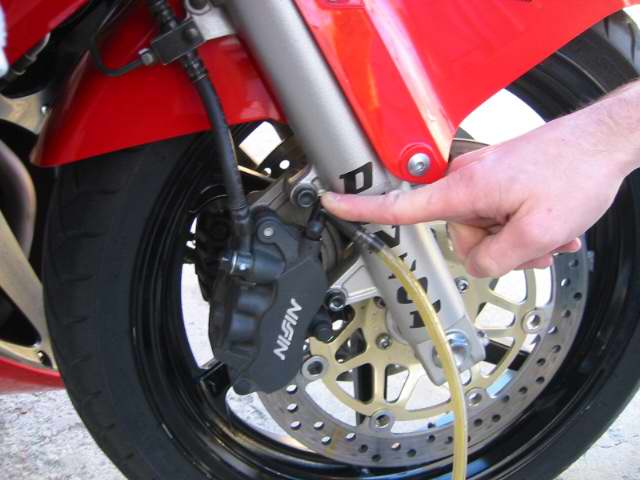
Push the SMC in with your hand.

Do not release from this point. Tell your helper to press the pedal again which will forcefully push the SMC out and then once your helper releases the pedal, you will manually push the SMC in again watching for new fluid. Once fresh fluid is coming out, I performed a final pressure bleed by tightening the LPCV bleeder, asking my helper to pump the rear pedal five times and release, then I loosened the LPCV bleeder screw and manually actuated the SMC gently half way and then tightened the bleed screw.

Note: Even with speed bleeders installed, I did not manually operate the SMC more than once for safe measure. To further elaborate on this; continuously pushing in the SMC numerous times will not bleed the SMC to LPCV brake line because there is no reservoir at the SMC. You will push whatever fluid is in the line and it will become empty with air. One manual push of the SMC followed by one rear pedal actuation by your helper.
D. Rear Caliper, Inner/Centre Bleed Screw Actuated via SMC

This procedure is the exact same as the above. The only difference is, you're bypassing the LPCV and going all the way to the rear caliper inner/centre bleed screw. Pressurize the sytem the same way as above too.

E. Rightside PCV (Opposite Battery), Single Bleed Screw

This is the easiest step. Follow the procedure as in Section A. but using the RMC pedal.

F. Rear Caliper, Upper/Outer Bleed Screw

Another easy step, follow above procedure.

G. Left Front Caliper, Inner/Centre Bleed Screw

The last procedure, again very easy, same as above.

Part 4: Assembly
Top up both fluids if they are low and fasten all caps and lids back on the reservoir.
Attach the front left caliper and torque the pivot and joint bolts to 23ft-lbs. The FSM says always use new bolts, but I cleaned up the old loctite residue, re-applied some new medium strength loctite and re-used them.
Attach the rear caliper and torque the joint bolts to 23ft-lbs. The FSM says replace also but I did the same as the front caliper bolts.
Reinstall the rear wheel and torque bolts to 80ft-lbs.
Now would be a good time to prime (pump a few times) your front lever and rear pedal lever. Once primed, they should not travel a lot of distance; they should feel stiff. If for any reason the levers travel a larger than normal distance, then there's probably air in the line somewhere or you might have forgot to tighten a bleed screw.
Note: The FSM says to use new bolts, not because there is something wrong with the bolts, but because there is probably some sort of loctite already applied to the threads. Thank you Metallican525 for that insight.
Part 5: Clutch
I don't have to go in to any detail about this because if you just did your whole brake system, might as well do the clutch as it's very simple and same procedure at Part 3, Section A. Remember to turn the handle bars to the right though.
At the end, I took my bike for a ride and I had no idea that this bike has this much braking power! Mind you, my fluid was 6 years old which was probably the cause of that but this method works flawlessly.
I hope this DIY was very thorough and gave you a good understanding on how to tackle this easy but tiresome procedure!
Clutch
This is cake if you just did your brakes! remove the cap to the clutch fluid, suck it out or use a rag.
The bleeder bib is on the clutch slave cylinder near the kickstand
 (
(
Bleeding a standard VTEC
We began by removing the seat and prepping the back area for work. Take off the 2 black Plastic pieces on both sides of the tank. Actually its not necessary to remove the piece on the right side but It could be a bit of a hassle to deal with.
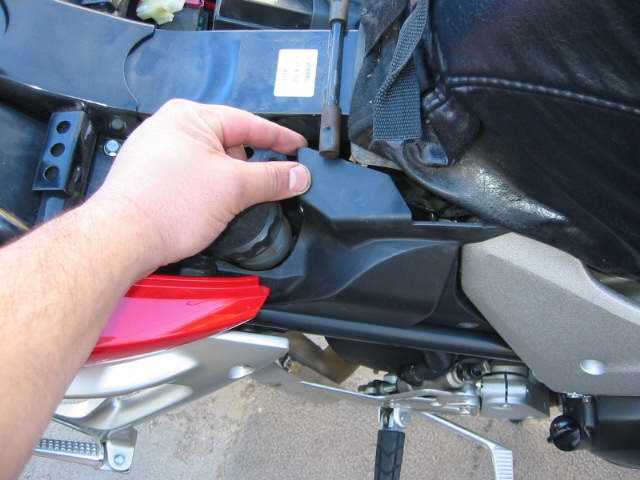
Removeing the Plastic on the right side
With the plastic removed you have more room to work, push in the center of the plastic clips to remove them.
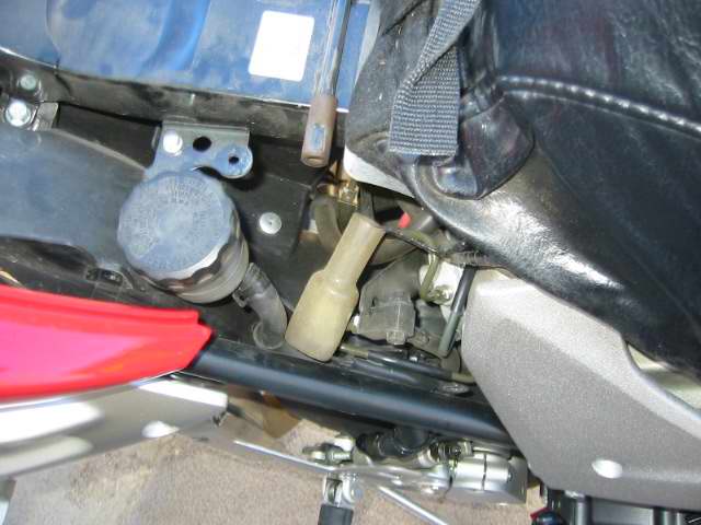
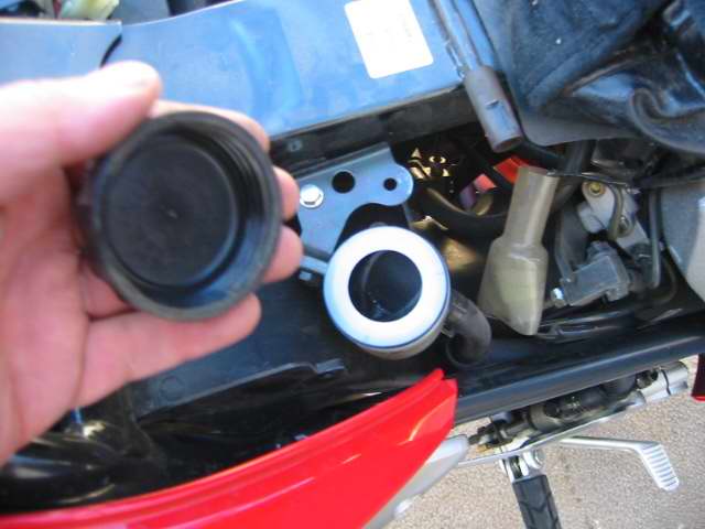
Proportion valve bleeder on the left side
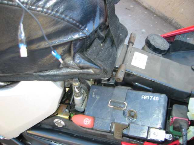
Left side removed covers the proportion valve and battery
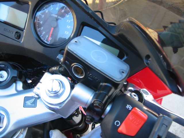
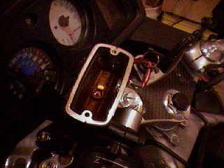
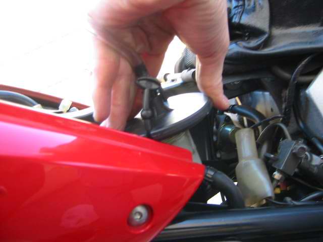
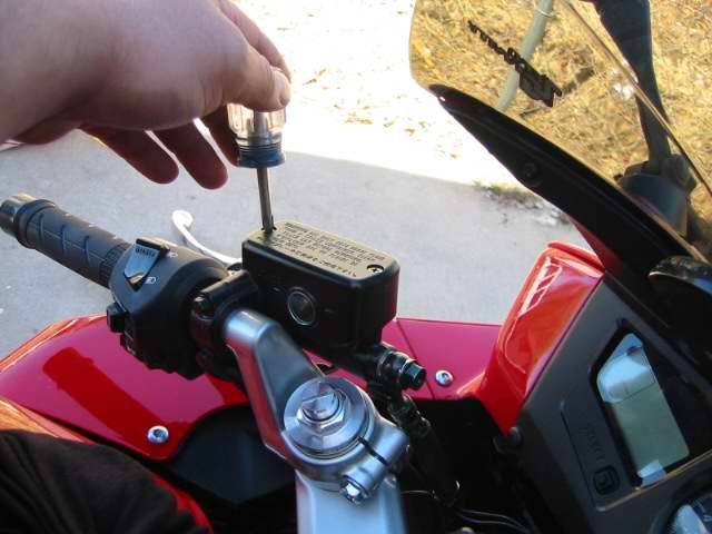
Turn the handlebar to level the master cylinder remove the cap, plate, and diaphram
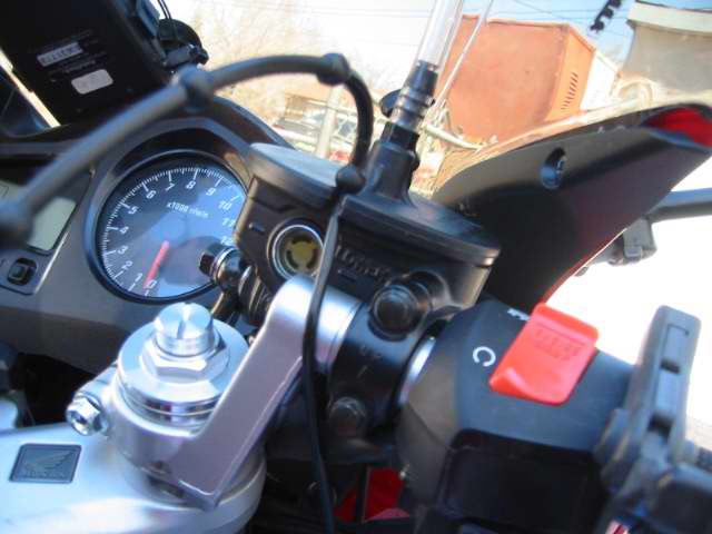
My vacuum bleeder has an auto filler that seals off the master cylinder and siphons in new fluid from a fill bottle.
Begin Bleeding The front Brakes
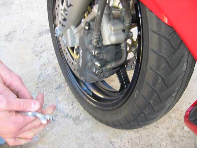
Begin on the right side top bleeder (its the only bleed valve on the right front)
You vacuum until its clean fluid then pump the bar hold it and close the valve. You will get air in the bleeder line its unavoidable, just make sure its clean coming out.
Cruddy fluid still coming out
Now go to the left side and do the top valve.
The bleeders on the calipers are 8mm, after you get clean fluid pump the handle again hold it and close off the bleeder
Top off the master cylinder and your done with the front, put the cap and stuff back on.
Doing the Back Master Cylinder
Remove the cap and diaphragm
I suck out the master cylinders first and top off with new fluid before bleeding.
The siphon filler would not seal cause of the ABS plastic was holding it up.
If you spill brake fluid clean it up with soapy water right away or it will eat the paint!
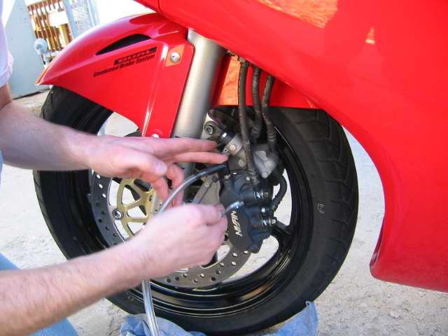
The center valve on the front left caliper is connected to the rear master cylinder start there
They recommend that you remove the caliper and hold it at 45 degrees to help the air bubbles float out, they also say to replace the calipers bolts when you remove them. NAH! Power bleeder!! I just push on the secondary master cylinder above the caliper to pump the air out.
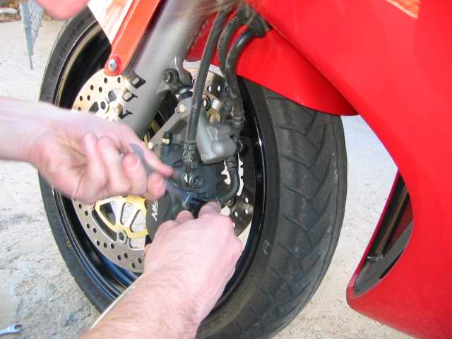
Push on the caliper forward to pump the secondary master cylinder
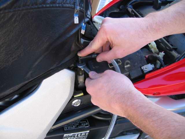
The Proportion valve wont bleed at all until you pump the petal, its 10mm wrench
Top off the rear reservoir so it doesn't go dry, start with the rear top bleeder
The old fluid is very dark! you will use a lot of fluid to do the VFR! almost a liter, we used synthetic Valvoline brake fluid.
Getting to the valves on the rear caliper is a pain in the butt
you can see a glimpse of the top bleeder in this shot
Again pump the petal hold it and then close the valve, do the front valve after the top valve.
Clutch Line
Remove the cap, suck out the bad fluid, top it off
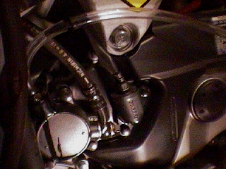
Location of the slave bleeder on the left side of the bike
Check the firmness of the levers and petal and make sure the clutch operates. If you feel spongy then you still have air in the system you will need to re-bleed!
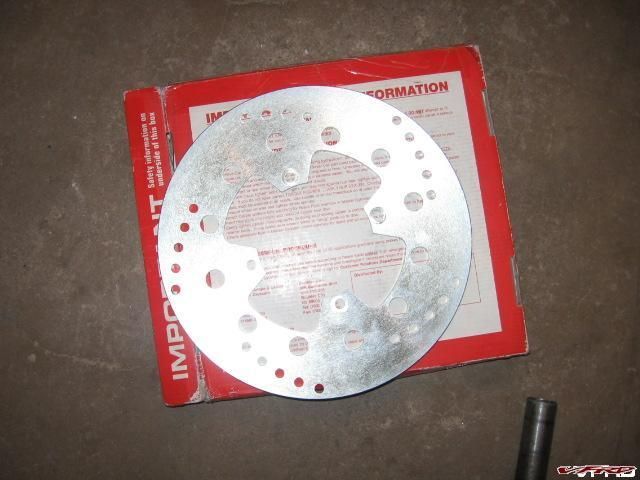
EBC replacement billet stainless disc
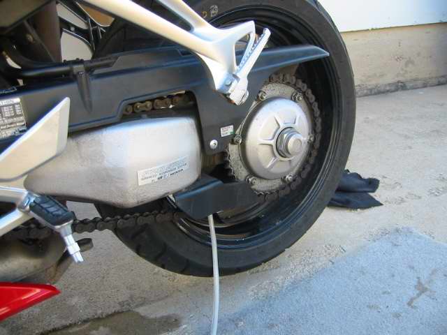
I have been noticing a pulsation in my rear brake petal at high speed, I suspected a warped disk and so I inspected it last time I was changing my rear tire and it was warped out of spec (0.012in) runout it was way over that at .03in. I notice the pad was dragging and that must have overheated the disc to warp like that.
Thanks to Rob M moderator here I was able to bid on a new one cheap on ebay from a seller here in Colorado. The EBC billet stainless unit I bought was a smidgen lighter and supposedly has more bite with brake pads, haven't tested that yet (too damn cold to ride today).
THE PROCEDURE
You can take off the disc bolts without having to remove the axle but it is tight and if the bolts are frozen like mine were it may be impossible, in any case you must remove the caliper to free the disc. I tried to with a 12mm boxed end wrench on one side (side facing the swing arm) and a 12mm socket on the other. It loosened one but the others were stuck, and there is very little room to work. I had to remove the axle.
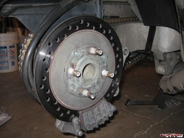
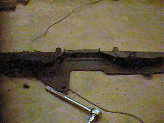
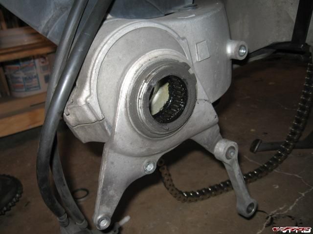
Old Disc shown rear wheel removed
I had a rock stuck in the pad and it bore a groove on the inside of the disc too, it was tiny but just enough to grind away at the rotor.
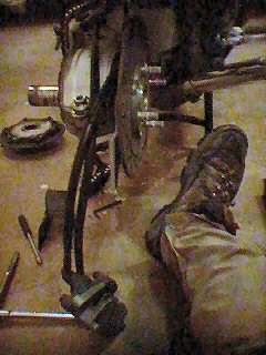
Craigs big socket - I did not have access to this time.
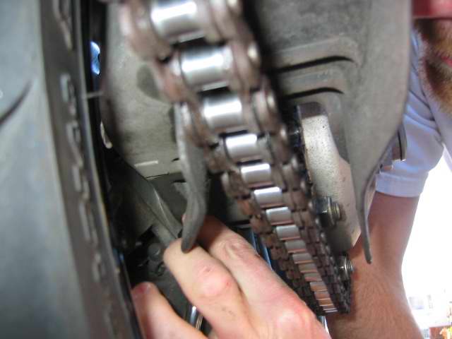
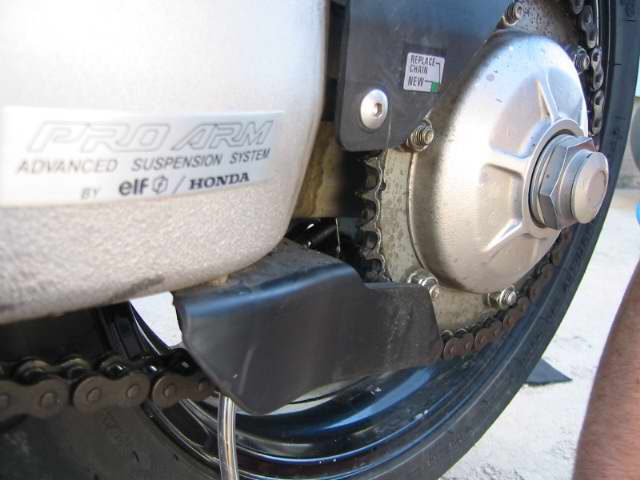
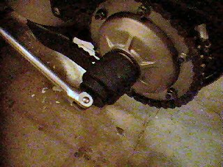
I decided to remove the big nut on the hub, its huge like 35mm or something like that, my Friend Craig actually bought a socket for it but he wasn't around so I ended up using a big old pipe wrench, the nut was already a bit chewed up so I just went at it. It came right off. I loosened the bolts on the chain stays to allow room to remove the chain and the cush drive. (loosening the eccentric hub bearing holder pinch bolt and using the chain tool to loosen the chain).
http://www.vfrdiscussion.com/uploads/chainadjust.jpg[/img]
sometimes its easier to remove the chain stay but I just took off the aft bolts to let is flop around so I could remove stuff.
Pop off the cush drive it just slides off the splines.
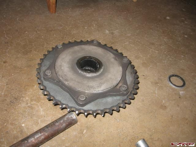
Cush Drive This just slides off the splines of the axle, as long as the chain stay is not in the way, and the chain is removed.

Removing rear Caliper
Removing the rear caliper is easier with the cush drive off so you can fit a socket on to the bolts, otherwise a boxed end wrench will work, the cush drive gets in the way, remove the two bolts off the swing arm caliper hanger. I also removed the hex bolt out of the dog leg to let it swing down to were I could get at it better.
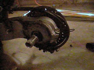
Ecentric hub needle bearings inspect and lube bearings.
At this point after the caliper is removed you can just pull the axle out of the eccentric. I noticed one of the pads was not seated properly?? OK that was the trouble eh and the caliper did not float properly sliding on the two pins, it is supposed to be able to slide side to side and float with the movement of the rotor. I worked it back and forth and would then slide freely. It has rubber boots over the pins one was ripped, I need to order new boots, I just slabbed some grease on it for now. I put in new pads while I had the caliper off.
caliper removed.
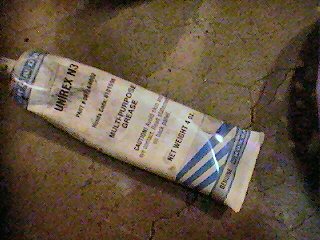
I used Honda grease on the bearings and the caliper pin that had the torn boot.
Ecentric hub needle bearings inspect and lube bearings
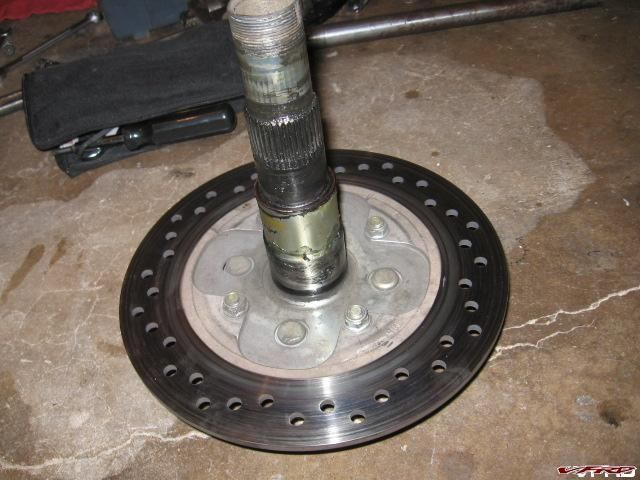
Rear Axle Removed Bolts are now accessible 12mm on both sides, use a narrow or thin 12mm socket as the bolt heads are recessed inside the carrier on the other side
I put on the new rotor and reinstalled the whole thing. There is a spacer place between the rotor and the carrier don't lose it, and make sure to follow the arrow on the rotor so that it rotates in the correct direction.
after pushing it back into my bike shed it rolled much easier!! Job done!
20K Valve Check
After Riding to California and back I thought it was a good time to do some major maintenance, replace the front tire that's cupped, 8k miles (not bad) oil change, clean the K&N airfilter, and check the valve clearance.
Began by removing the upper and lower faring and seat.


This is also a good time to clean engine parts of dirt and build up I removed my K&N filter and soaked it in water with laundry detergent. Remove the Gas tank clamped off the gas lines.


Remove the reedvalve tube, and unhook the rubber bib to get to the rear cylinder head, remove the 4 10mm valve cover bolts then lift out the valve cover, remove the pulse cam cover on the side that accesses the timing hole.


Remember there are 4 valves per cylinder the 2 on each side, exhaust on the outside of the V and intake in the inside of the V the cylinder cover also tells you which piston number is which. Rear left cylinder #1, front left #2, rear right #3, front right #4. I have done this before on another post so I wont repeat myself just add things I didn't mention before.
This is the rear cylinder head.

I turned the crank till the timing line was lined up with #1 and both cam shaft lines pointed out, this is the compression stroke. I don't know if you can see the cam shaft lines I highlighted the lines since they are hard to see.
Set the crank for Cylinder #1


Check the clearance on cylinder #1, use a .006" feeler gauge on the 2 intake if its tight, if not then move to a .007" it shouldn't fit, you will have to replace the shim if it goes past this make sure to do both of the intake valves, then go to the exhaust side start with a .012" feeler if its not tight go to a .013" if it goes past that replace the shim. Do this for each cylinder. You have to put a bend in the feeler gauges to reach in
Now Cylinder #3 also on the rear side of the bike.
Check the clearance on #3

If they are in spec replace the cover, use sealant on the round part of the cover gaskets. Bolt it back on. Then move to the front. Drop the oil cooler and the 2 radiators, there is a radiator sensor which must be unplugged on the left side, remove the bolt and gently side it off the upper and lower holder pins do the other side then let it drop down out of the way. Remove the oil cooler bolts and drop it down.
Remove the cover then move the crank to #2 position.
Check the clearance on #2


Move the crank and Check #4


All mine were in spec again!

Hello All,
Cleaned up the pitted pistons on a set of Nissin radial calipers from a Triumph Speed Triple (being fitted to the 5th Gen front end conversion). Process is the same whatever calipers you have.
Pistons removed and you can see the corroded/filthy bits on the exposed portion of the piston lip. The exposed takes all the hearing/cooling/salt spray abuse and are not protected by the caliper. No surprise they look like sh!t.

Dirty pitted one on the left. Polished one on the right. Pitted big piston on top.
Method: lay some old material (denim works best) on a flat surface, apply some metal polish (I used Autosol) and rub the piston up-and-down along the corroded section. See the black streak in the picture above.
This is really smooths down the burrs and the phosphoric acid in the polish helps the newly exposed metal form a protective oxide layer.


Pitting will never be completely removed but it certainly gets smoother. Piston on the left was dangerously pitted and could easily have ripped a seal if pushed into the caliper. Now it is brought back into serviceable shape.
Next, clean off the polish residues with brake cleaner and apply a dab of superglue on the worst pits. Superglue will adhere to the new oxide layer (and any remaining rust) to protect the areas where chrome has failed.

Let the superglue dry for at least an hour as it takes ages when left open like this. Then run a new razor blade over the glue to remove the blobs that stick out. Scrape it both ways.

Final rub down on a clean cloth to smooth everything out and you’re done!
Good for another season.
Caveat: a pitted piston will not be improved by this method - it will only get wise with time. Also, don’t rub too much of the existing chrome away as you will end up with failures elsewhere soon. Always install with a good amount of silicone grease/brake paste to prolong protection.
I wonder why we still use steel pistons when anodised alloy and even better, plastic, could be used to better effect.
Hope this helps someone out.
Best,
Stray
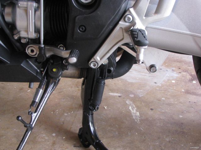
Center stand installed and lifting the bike up
These are the steps to installing an oem centerstand for a VFR1200F Part Number 08M50-MGE-100 This retails for around $200 delivered, I got mine from ServiceHonda.com. Before even attempting to do this MAKE SURE THE BIKE HAS COOLED OFF you will be working around the headers and you will burn yourself if its hot!
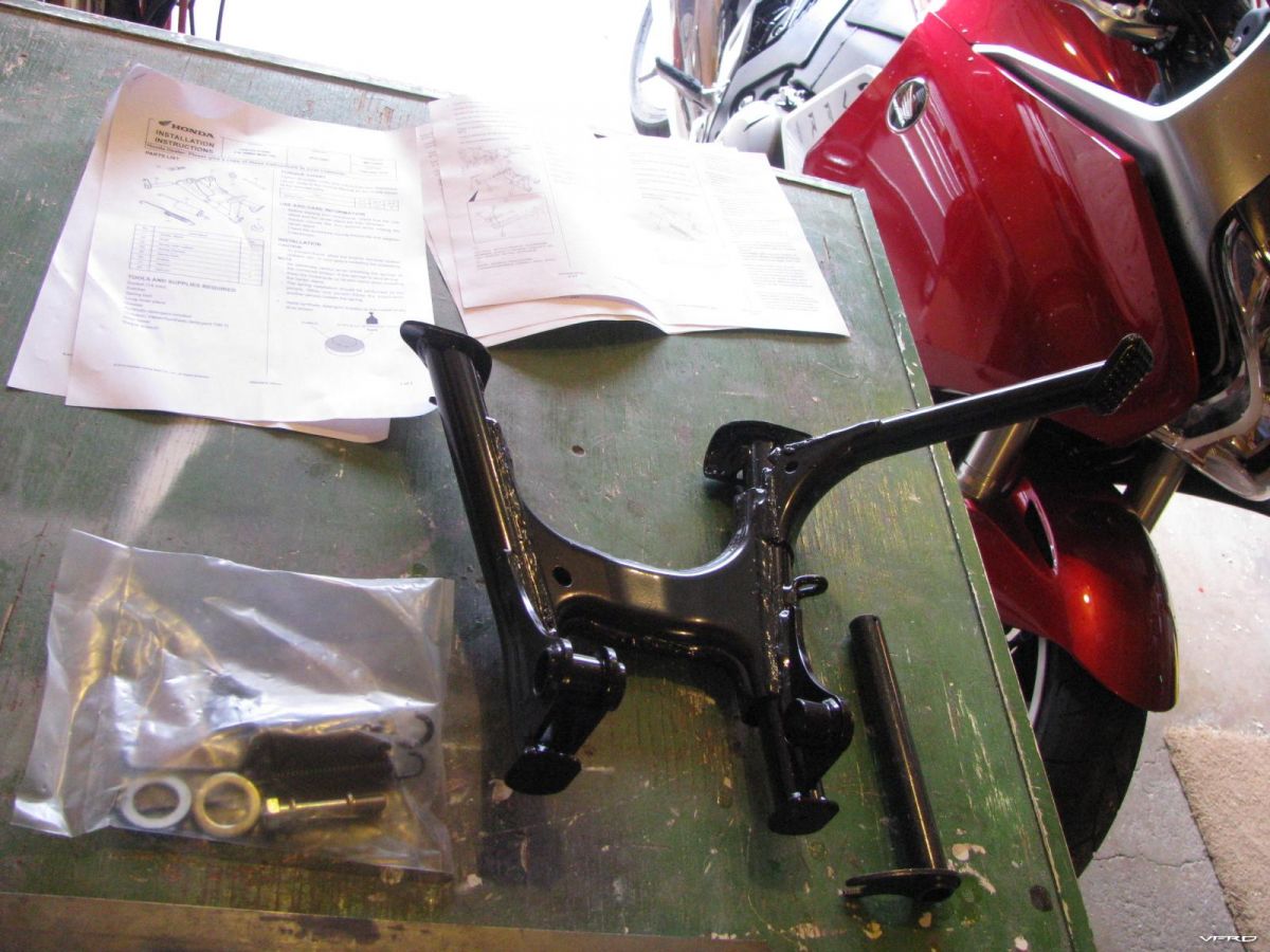
Centerstand parts and instructions
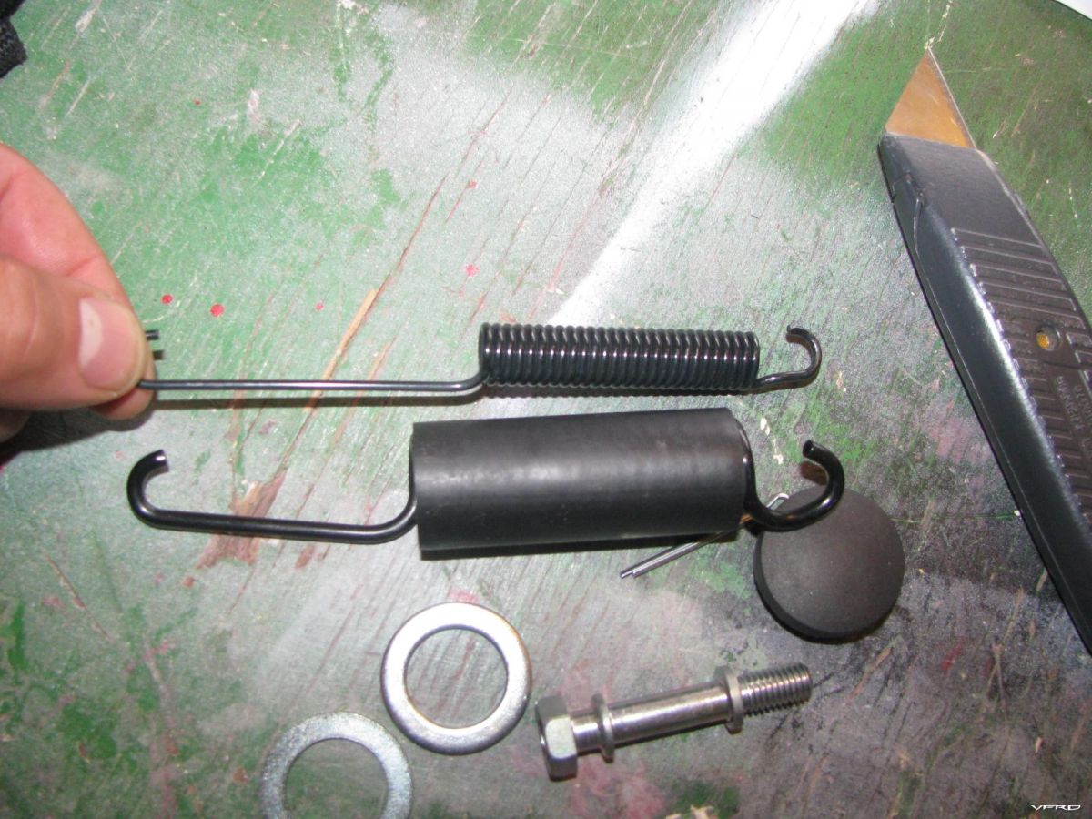
Inner and outter springs main spring and a safety spring that fits inside
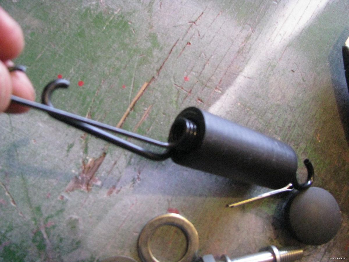
Should the main spring break the smaller saftey spring inside will keep the centerstand up so that the centerstand does not fall during riding causing an accident
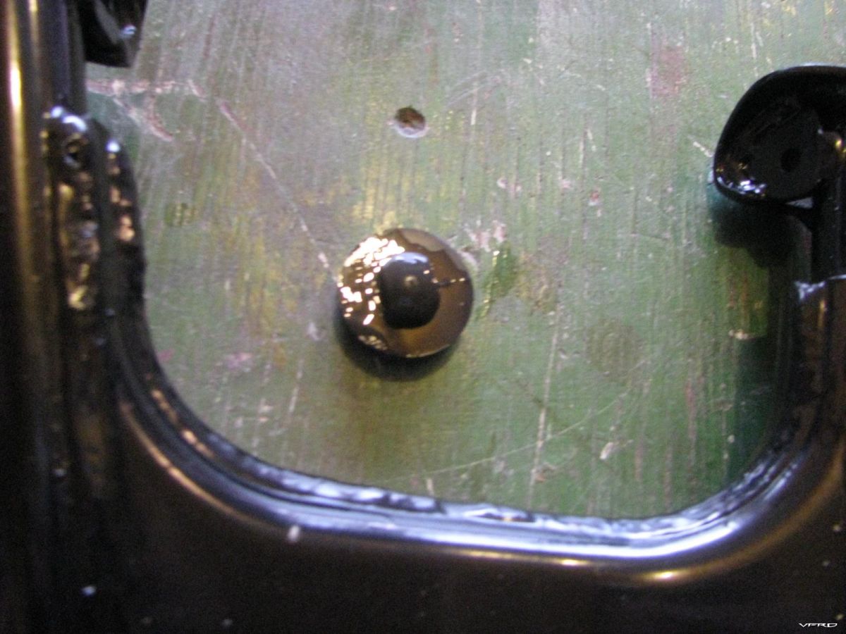
Bump pad wet with soapy water to install inside the hole in the stand
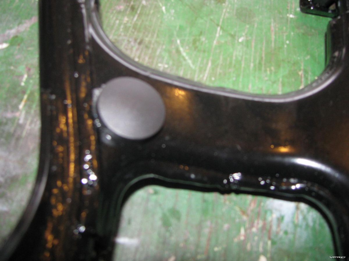
Twist and push on the bump pad until the pad seats itself inside the hole
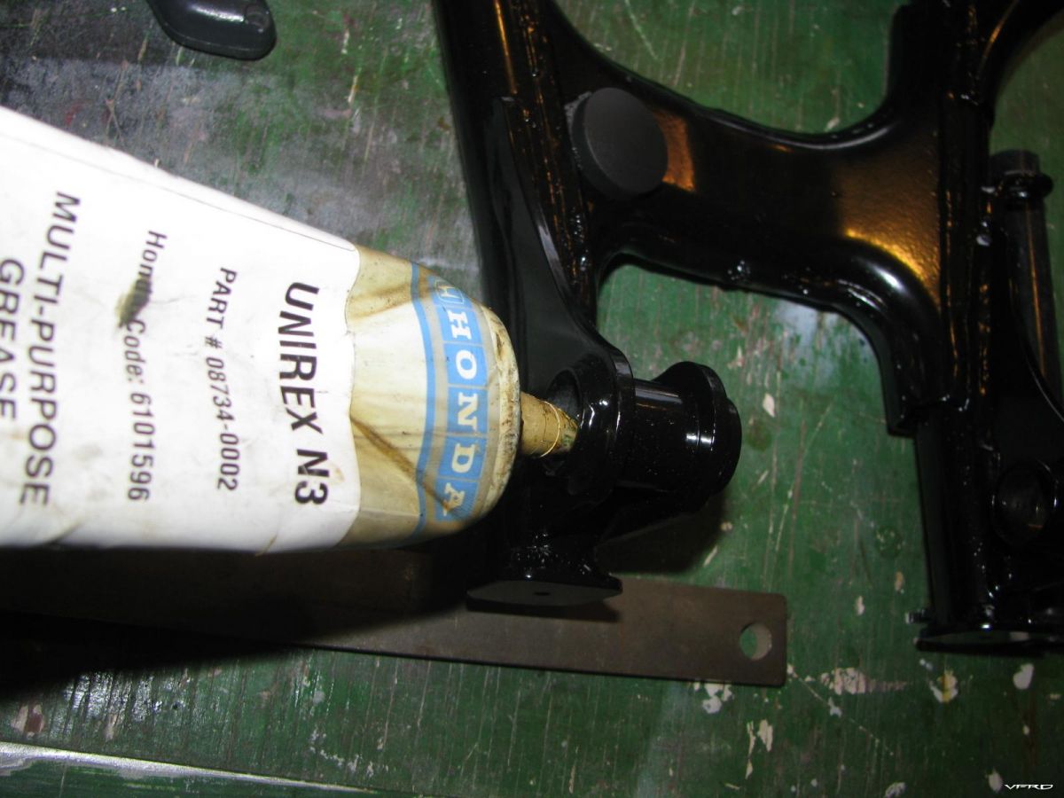
Grease the post holes
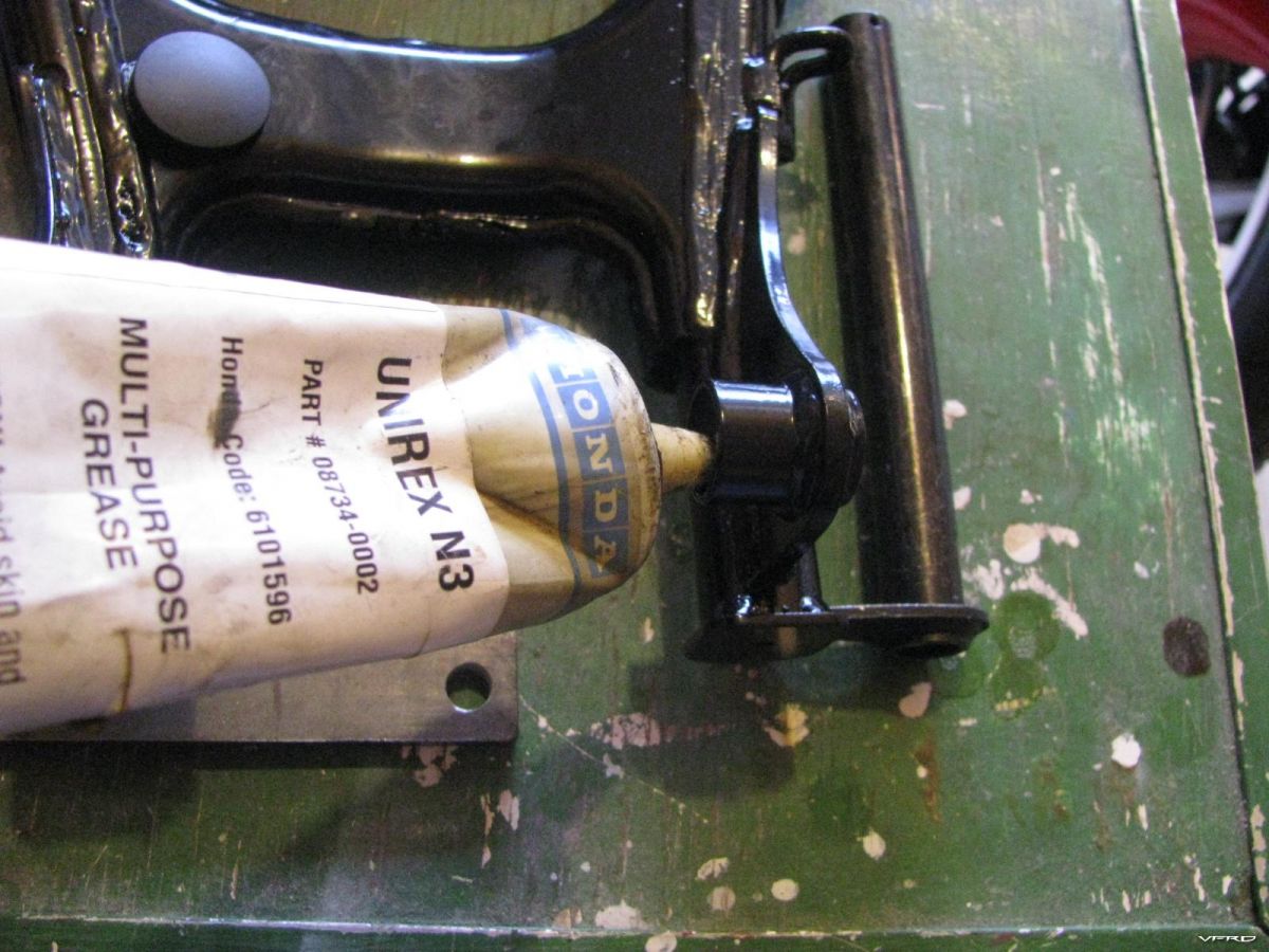
Grease the other post hole
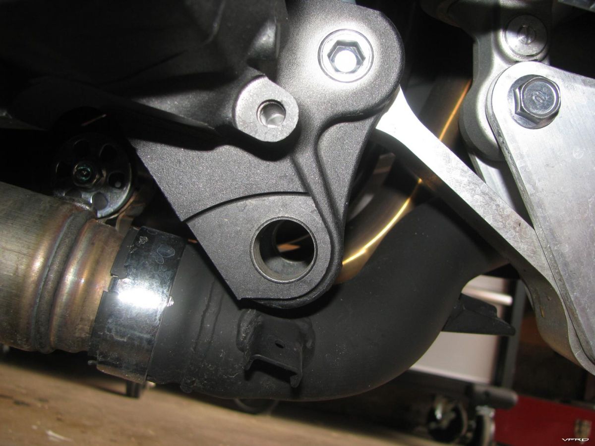
This is where you will install the center stand post goes inside that large hole and the spring hook in the upper smaller threaded hole
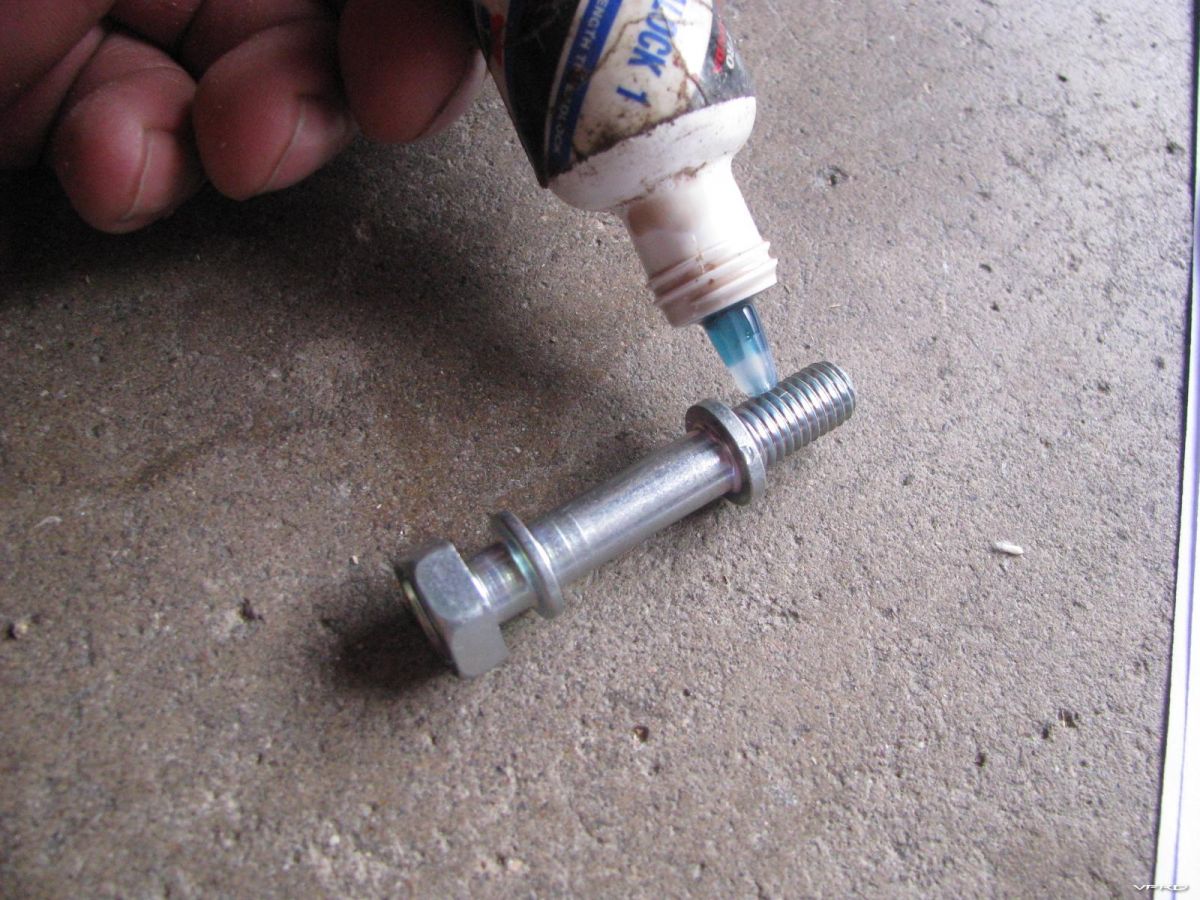
I used Honda thread lock on the spring hook bolt I dont want it falling out
The bolt is a 14mm bolt and the torque spec is 16 foot/lbs
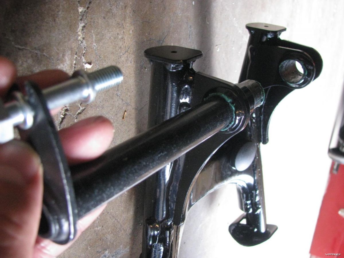
Dry fit This is the basic layout of the centerstand mechanism
Here I am trying to install 1 of 2 washers on the right side washer 1 goes inside the right stand post hole 2 on the outside of same post hole
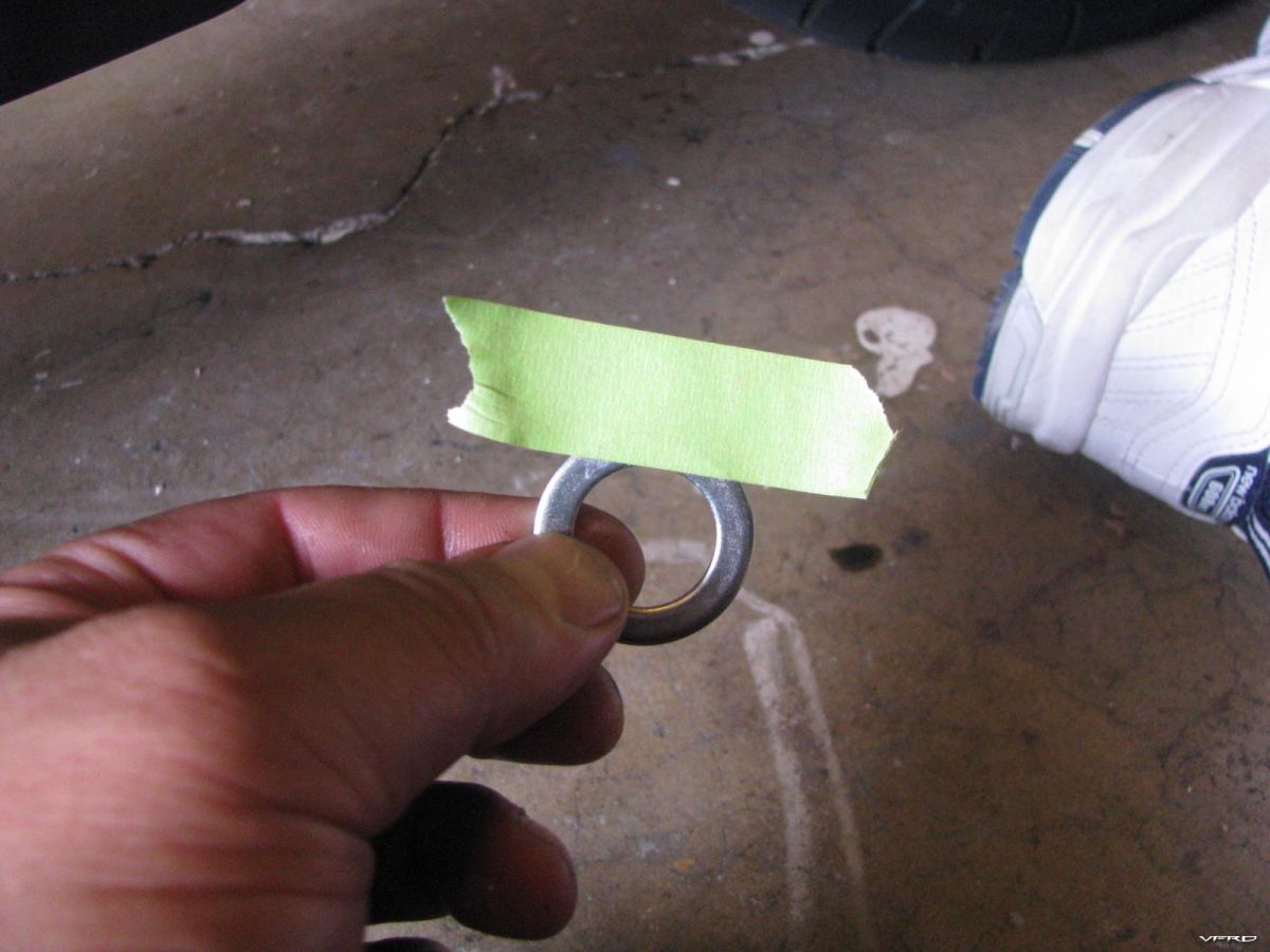
I had difficulty holding the washer in place so I taped it in place with masking tape
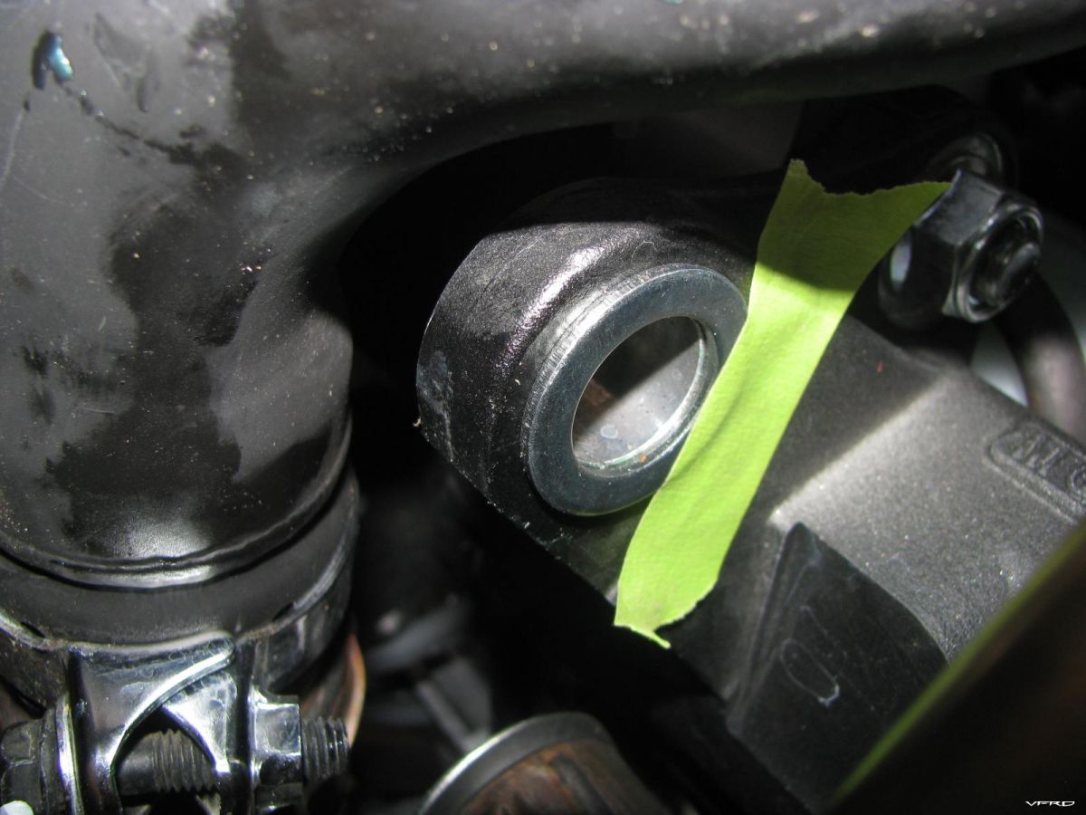
washer 1 taped into place
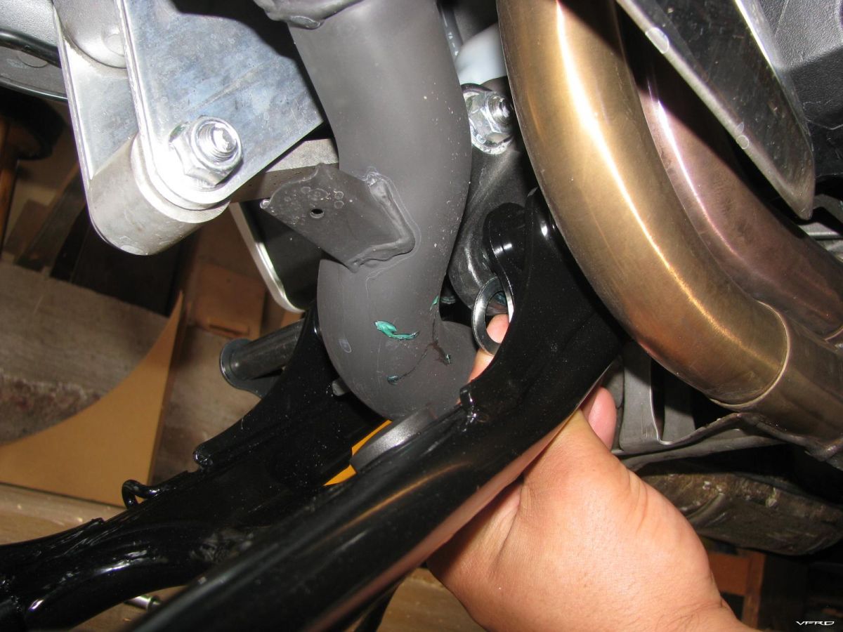
I slid the post into the post holes fitting washer #2 was also a chore not much room with the headers there
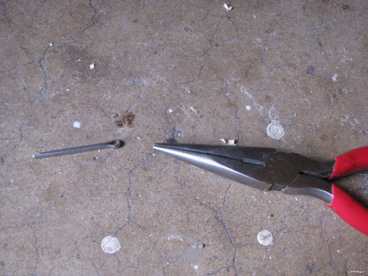
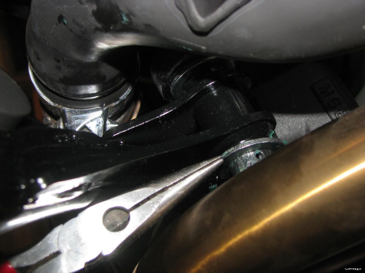
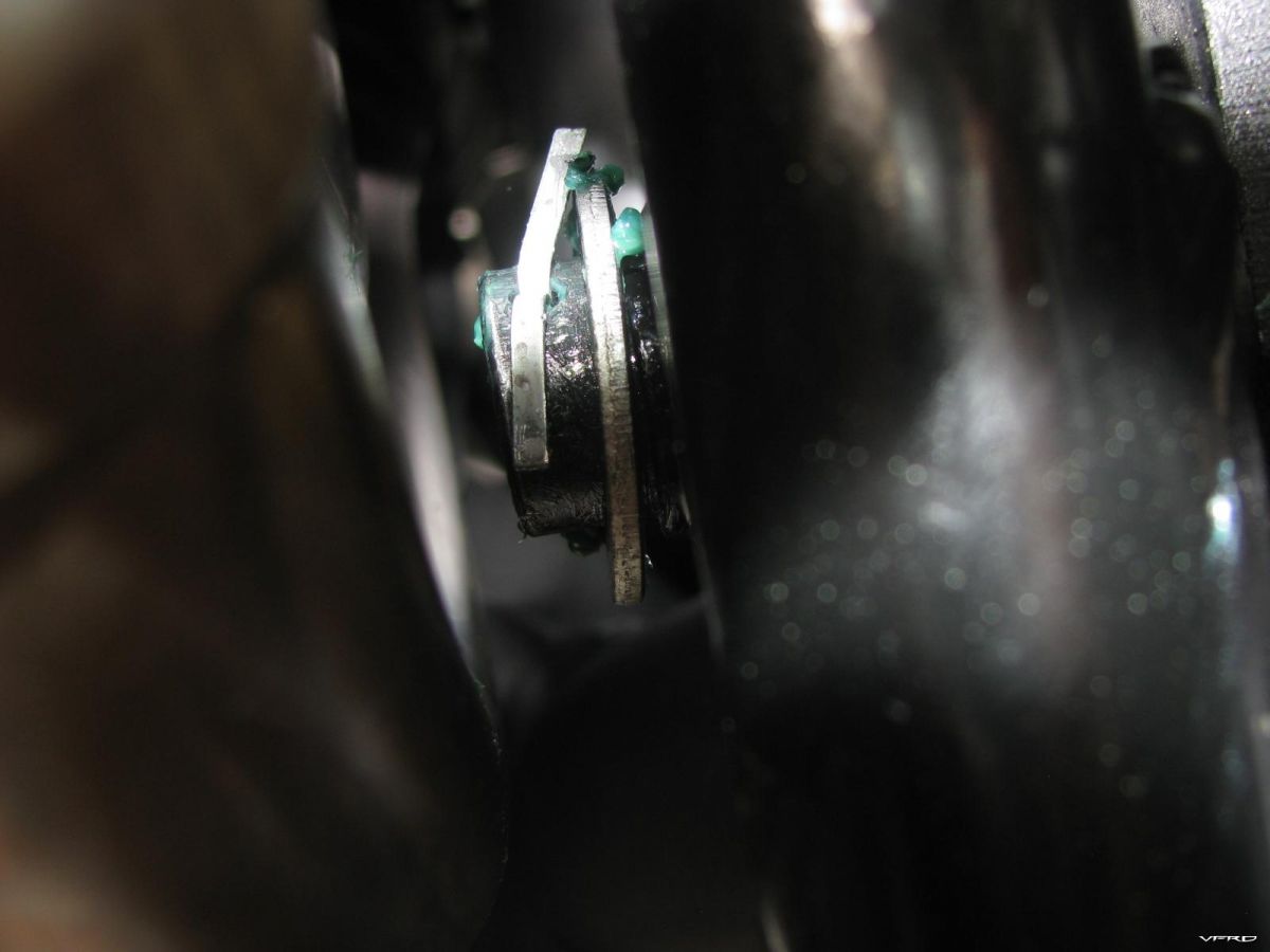
side the cotter pin into the hole in the post right side fingers or use a needle nose
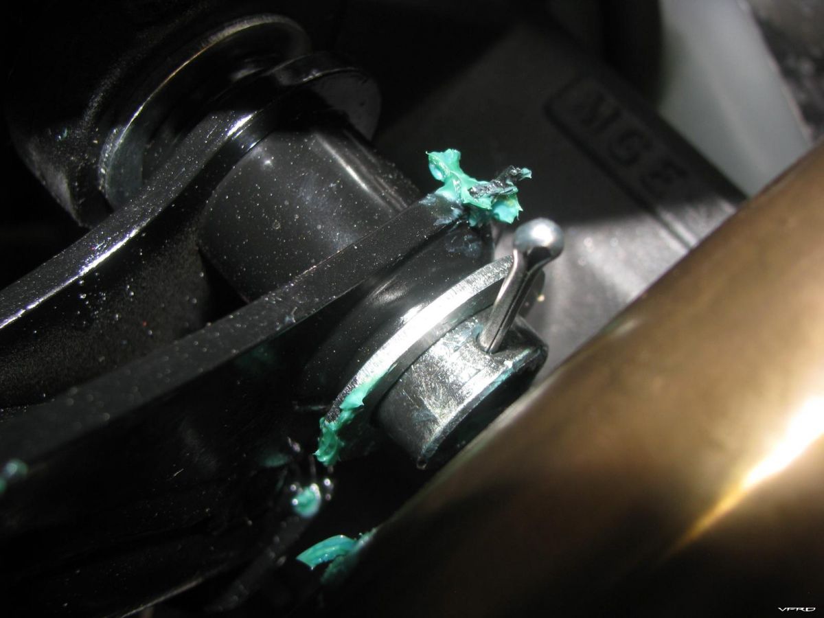
cotter pin goes here right side
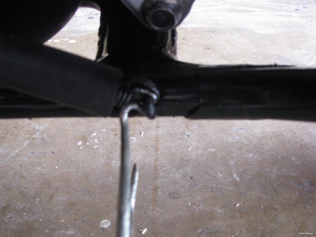
spreading out the cotter pin ends is difficult to reach a flat head screw driver did the job from the front on the right side of the bike
installing the springs I used an old spring installer my Grandpa had for drum brakes - instructions call for two persons to install the springs
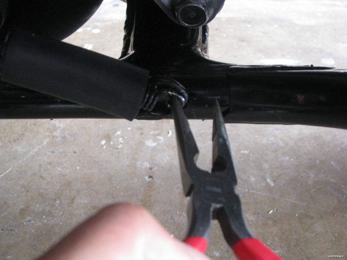
The safety spring did not go on the first time needle nose pliers for that

I began with a strip down of the basic plastic removal around 3am in the morning, I work nights anyway and well it is a quiet time for me with no interruptions from nosy family members! That took no time at all I am getting pretty good at removing the plastic.


Yes you have to remove all that just to get to the front spark plugs, lucky they use high mileage iridium spark plugs with a 30k lifetime so you are going to have to inspect the valves before hand before you have to replace them - I did that and they all looked fine. I had all of my exhaust valves just out of spec those are the rocker roller set, and one of the bucket under shim intakes was loose but still in spec. Just as I figured the roller rocker design would be more apt to be out of spec then the bucket under shims would be, just like the CRX dirt bikes! Its a simple elegant design, less rolling mass with only one cam shaft and the cam chain does not need a huge bend in it for a powerful cam chain tensioner this design uses a spring loaded bow tensioner instead of a massive punch design like the vtecs use.


There are two marks on the timing cover I suppose its easier then the 4 I had on the old girl, you watch the cam shaft on the rear set for direction ques as you turn it to make sure the engine is in top dead center for the cylinder your inspecting all marked out in the manual but the manual has very small pictures for the cam shaft positions so its hard to read. I managed it though. They have 3 measurements for the Valve Clearance
Exhaust Valves have a roller rocker design with a roller on one end and a screw driver and lock nut on the other with a square head for the driver. They were all out of spec all of them!
The manual has two sets of measurements for the exhaust side
Valve side with the lock nut 0.03 + or - 0,02 mm or (0.012 + or - 0.001 inches)
Roller side 0.21 + or - 0.02 mm or (0.008 + or - 0.001 inches) my gap strips were in listed in both but came stepped up in inch sizes so I use the inch listings
Intake side is the shim under bucket design
0.16 + or - 0.003 or (0.006 + or - 0.001 inches) on one was loose at .007 but still in tolerance and most likely to go tight as it wears.


Edited some of the photos with additional info that I neglected to mention first draft. I started at 3am and had it done and back together with the bike running at 6am. Including a half an hour bathroom veg out break, take your time, be diliberate, read the manual for instructions, read all the back pages for what to do and dont take any short cuts be careful removing connectors and fasteners they can get dropped easy - calm slow and methodical is best. If you dont have much time to do it then just let a pro do it or wait till you can dedicate all your attention to it and not hurry the job. Break it up into sections/tasks and it wont seem so difficult. Each task one at a time then reverse it to button it all back up.
Hello all, I was wondering if there is a step by step guide on disassembling and cleaning calipers on gen 5 vfr800fi?
I came across this article and video and thought that it might be of use to anyone attempting to repair broken tabs on their fairings. Remember to always look at plastic Type code on the inside of the fairing before you buy the appropriate adhesive.
https://diy-auto-repair.wonderhowto.com/how-to/fix-broken-plastic-tabs-bumper-0141489/

Hi guys,
As you all know I have been having a heck of a time with my 2000 VFR. It suddenly would loose power and then gain it back without any throttle movement.
I did all the things you would normally do to fix this prob: plugs, check for spark, drain tank, injector cleaner, check connection, check vacume hoses, check battery etc.
I finally said I'm gonna change the fuel filter (thanks Slammer) and I read alot of post saying it was a pain in the Azz.
To tell the truth I would rather do this job than take the fairings off.
Step 1. Empty the tank.
Step 2. Disconnect all conectors and hoses from tank.
Step 3. Remove tank from bike and turn it upside down.
You will see 5 nuts (pink arrows). Simply loosen them off as you would a tire (star pattern). They are on with blue locktite so they are a bit stubborn but not too bad.

fuel filter 1
Step 4 Remove the fuel pump assembly. The first thing to note is that you must lift the back of the assemble up and out (by back I mean the part of the assembly closest to the end of the tank). When you begin to lift you will see a flat piece of rubber, just grab it with your fingers and work it out. Next thing you'll see is what looks like a metal scrubby you use to clean dishes(at this point I almost shate myself) RELAX it's part of the sock filter. Now the sock filter is long and travels from one side of the tank opening to the other side of the opening. (rear to front of tank) So you have to bend it a bit to get it out of the hole. Don't worry its plastic and pretty flexable. Once the sock filter is all the way out you can lift up on the remainder of the fuel pump assembly and take it completely out of the tank.
Step5. Removed the clips(Pink arrows), remove the screw and bend the bracket out of the way and take out the fuel filter.(the gold thing)
.
fuel filter 2
PS I cant believe this thing cost 80 bucks!!!!
Step 6. Replace with new filter.
Step 7. Re-install the fuel pump assembly. Ok now remember the fuel pump goes in with the sock and scrubby facing the front of the tank. When you get it in the hole until the sock meets the tank, you will have to bend the sock down and into the tank, stuff in all the metal scrubby thing, and then the rubber piece. Once its all in apply blue locktite, tighten the nuts in a star pattern as per the service manual, then torque as per the service manual.
Step 8. Put the tank on the bike, connect all hoses and connectors, fille with fuel and test
The result for me was a complete(or so it feels right now) success.
I finally have the power back and took it for a decent run and it didnt revert bak to the surging thing at all.
When I got home I had to see what a 80 buck filter looks like. You guessed it a piece of cardboard folded like a normal filter. Nothing special.. I could feel with my finger alot of sand/grit on the outside of the filter paper, so I'm guessing it was restricting the flow enough to conk out the bike. Although I have to admit I was thinking I was gonna find a pebble in the filter opening, but I didn't.
Anyways guys, if you ever have to do this job, it aint to bad just be very carefull not to drop the pump...she be a tad expensive
Damn it.
Due to a rarity of riding this wet CA winter, two of my bikes won't idle without choke. I've had Stabil in the tank since last fall but apparently it didn't work worth a damn. I tried Seafoam in the tank (ran rough with smoking, naturally), then straight Seafoam from a small external tank directly into the fuel line (smoking), then drained all the float bowls and ran straight Seafoam from the external tank again, cut it off, and let it sit for 72 hours. One bike (gen 4) got to the point it would idle enough for me to take it for a hard and fast ride, but it surges up and down 2000RPM when idling on it's own.
It ain't right. Slow to come back down from revs too.
The OTHER V4 (1st gen) surges on idle up and down, won't run off choke, and won't move (dies instantly) when given gas.
Seafoam helped a bit on the 4th gen. Should I try it again? I REALLY don't want to pull these carbs off. I really don't. All of this could have been solved if I had just ridden the damn things more this winter. Ugh.
My inline four had the same issue, but I pulled the carb bank and cleaned the jets in about 40 minutes. Super simple.
Anyone got any wild-arse ideas that might work to avoid having to do this? My neighbors won't like the Seafoam again, but....??

IMPORTANT: This “how to” is based on the Honda Factory manual technique for the tensioners replacement. If you read down a few replies you will see that a number of people have been successful at replacing the front tensioner without pulling the throttle bodies.
Cam Chain Tensioner replacement, Vtec
By rad
Why:
Because it is one of the few Honda weak points, common to many models, and mine at just about 30K miles were making a loud racket once the bike was warmed up. Why did I write this up? I'm not a pro wrench, just a home mechanic who has gained a lot of knowledge these last few years from these types of threads and I like giving a little bit back when I can, here, and on the other forums I hang out on.
What:
There are two tensioners, both on the right side of the engine facing rearward. The forward one is located on the back of the right front cylinder and underneath the throttle bodies. Yes, the throttle bodies need to be removed to replace that tensioner. The rear one is located behind the right rear cylinder and can be accessed by just removing the semi circular heat shield located behind the right foot peg mount.
Skill level needed:
It is not a hard job but it is also not for the complete n00b wrencher. As with most machines, there is plenty you can screw up if you don't pay attention to what you are doing and you fail to think everything through. I wrote this with the fairly green (not Al Gore kind of green) wrencher in mind.
Disclaimer:
Everything you do to your bike, no matter what I write or anybody else states anyplace else is 100% your responsibility, just like when you climb on your bike and go for a ride. So, read everything here, the manual, and make your determination if it makes sense and how you want to proceed.
Tools needed:
Other than your normal assortment of smaller metric sockets and the hex drivers there are a couple of specific tools needed. Along with sockets and the few tools listed below I also recommend you invest the $'s and buy a factory shop manual.
• Torque wrench that reads accurately down to 12 Newton /Meters
• Loooooong Phillips screwdriver, 10" or so, #2 head works well, My 8" one barely reached. I needed one more inch; I know, my wife has been tell'n me that for years….
• Cam Chain tensioner release tool. How cool is this, it comes with the new cam chain tensioners. Save this tool for it is the same one you need to make if you do your own valve adjustments.

• Good flash light; and if you are working alone, don't laugh, but a camping head lamp is invaluable during the work underneath the throttle bodies.
• A bike lift sure helps. If your cheap like me consider the fact that the money you save on labor doing this job will not only pay for a Harbor Freight lift, you will have some $ left over

Wrenching aids:
Good music always helps, hard to beat these guys,

This goes well with a bike and a garage. Please note; the amount of use of this wrenching aid can be inversely proportional to quality workmanship.

Parts needed:
The tensioner is the big ticket item, about $100 each, you need two. There are a couple of other assorted pieces that Honda recommends replacing at the same time; you can decide if you want to replace them. I just replaced them all, I was in there anyway and they were relatively cheap.
2 Tensioners
2 Gaskets

2 Tensioner Washers

2 Tensioner bolts

2 Tensioner Buckets, (real name?)

Tips before you start:
I never trust my memory! I have found it very easy to forget where a bolt or washer goes or where a cable or wire is routed, just a few hours later when it is reassembly time. Solution, for me I do one or more of the following on disassembly.
1. I use my digital camera and photograph every step, especially electrical wires and hose routing for quick reference upon reassembly.
2. I zip-loc bag and mark loose parts
3. I have a hard bound note book I keep detailed notes and sometimes drawings in, if needed.
4. I apply painters tape to each connection I take apart with matching numbers written on them.
5. My favorite; I just thread the screw, bolt or nut right back where I just remove it from. That way it can't get lost and it is right in place for when I reassemble the fitting.
Step 1
Lets start easy; the rear tensioner:
Remove the black metal semicircular heat shield located just behind the drivers right foot peg mount. It is held on by three bolts. Remove the top heat shield bolt first.

The manual does not state this, but I had to remove the right driver's peg assembly, two large hex bolts, to get the other two heat shield bolts off.

This is because the lower two bolts, that hold the heat shield in place, have loose nuts and washers located behind the shield. Here I'm reaching behind the shield with a 10mm box end wrench to remove them.

Once you have the three bolts for the heat shield removed it pulls out with a gentle tug for the top of the shield bends over the top of the exhaust pipe.
Zip tie the foot peg assembly out of the way

Look, there is the rear tensioner

Remove the sealing bolt and sealing washer.

Remove the cam chain stopper tool from the new cam chain tensioner. Hold the rubber ended shaft with one hand so that when you pull the tool straight out it does not allow the shaft too spring out rapidly. If you have not figured out yet what the tool does, here it is; it retracts the spring loaded shaft on the tensioner, and locks it into place during removal and installation. The tool is inserted part way, rotated clockwise until it stops turning then the shoulder section is inserted the rest of the way after you line it up with one of the slots.
Insert the tool, rotate it until it stops and lock it into place in the still installed tensioner; I just used one of the tools I made when I did my valve adjustment.

Remove the two mounting bolts. It may be just me but I prefer to ease off each bolt a little bit at a time going back and forth between them when ever I remove cast type fittings.

Pull the tensioner out, pay close attention to the gasket and how the dimple on the "ear" is oriented, mine was with the bumped out part facing the cylinder.

Install the tool back into the new tensioner. Place the metal bucket (new or old one) on the end of the tensioner; put a new gasket on, just like the old one was. Insert the tensioner into place and tighten the mounting bolts. Nowhere in the manual does it specifically state the cam chain tensioner mounting bolts torque specs. There are two sections that make reference to cam chain tensioner flange bolts and guide bolts, these are both bolts located inside the engine, not the ones we are dealing with. I felt very comfortable using the standard 12nm noted in the VFR manual as the general spec for 6mm, and 8mm flange bolts. No thread loc is indicated anywhere.
Remove the locking tool and install the sealing bolt and sealing washer. I did not use 12nm here, my gut told me the lack of threads (very short bolt length) that 12nm was too much. It is just a seal, so I snuged it about "that" much. I just trusted my well worn Calibrated Wrist Wrench.

A tip here, when you are working with small fasteners I find it best to use the smallest drivers that will do the job, ¼ " works well here and helps prevent you having to post a thread titled something like, ( Is it hard to Heli-Coil?)
Ya did it! The rear is done and now you can reinstall the shield and foot peg bracket.
Front tensioner:
Ok, this one is not hard but if your kind of new to wrenching it may get a bit scary as you start to eviscerate and disembowel your beast. "The only thing to fear, is fear itself", just like our 32nd Prez said.
Remove the seat, This may be just me, a hold over from wrenching cars and bikes for years, I always remove the negative battery lead and zip tie it out of the way when I'm messing too far into an engine, removing gas tanks, or plugging and unplugging a number of electrical connections.
Remove both main fairing side panels; keep track of the 4 different types of fasteners and where they go back.

Drain the engine coolant using the drain plug located on lower portion of the water pump on the lower left side of the engine. Remove the radiator cap to do this. I had just changed my coolant a few thousand miles ago, so I saved my coolant in clean containers so I could just reuse it.

Be ready when you open the radiator cap after the drain plug is out, the coolant leaves the bike much like the proverbial saying "Like a cow piss'n on a flat rock".

Hopefully you ran your bike down to almost no gas; it just makes handling the gas tank easier. Remove the tank, first the two bolts by the triple clamp. Suggestion, place your hand under the tank bolt holes as you lift the front of the tank and remove both the long shouldered washers now before you hear a slight metallic clank as one falls out into the dark recesses of the frame and engine…Don't ask…..

Lift the tank, support it, I do it with a motorcycle cargo net hung from above so I can adjust it to any lift level I want. You can also use your tool kit tools as outlined in your owner's manual.

Remove the upper tank cable fastener.

Disconnect the two electrical connections under the tank at the rear by the fuel filter access plate. One is the fuel level sensor, the blue one, and the other is for the fuel pump, the brown one.

Pop the vent hose and over flow tube out from under the bendable metal keeper connected to the tank.. Rotate the tank 180 degrees and place it on the frame rails after you first place a thick towel down to protect the frame and tank.

Remove the air cleaner cover screws, un plug the air intake on top of the air cleaner and remove the air box top and the air filter.
Notice the intake stacks, note their positions for reinstall. Folks have messed with these positions, tall rear, short front, tall and short in front and the same in back, etc. So have I; I have never found any noticeable difference. But, I'm sure somewhere someone has increased HP by 20%, boosted gas mileage and cured the Vtec engagement surge just by moving their intakes. Trust your judgment here on reassembly.

You probably have more plumbing behind the air box than I have, I removed my PAIR Valve hoses, etc a while ago. Disconnect the hoses (if you still have them) to the PAIR Valve solenoid; unplug the map sensor and the vacuum line below it. These are at the rear of the air box.
Stock photo of plumbing back there

Disconnect the #12 vacuum hose and the grey connector near it. Both are located on the right side of the air box near the front. That is the grey connector and the hose leading away to the lower left from the brown one way valve

Lift the air box up and disconnect the IAT sensor under the air box.

Unhook the idle screw adjuster from its keeper, just below the frame rail on the right side. Note: in a few minutes, when you are ready to lift up the throttle bodies, you need to carefully help guide this fitting through the frame openings in order to allow the throttle bodies to be lifted.

Remove the two shouldered mounting bolts to the coolant over flow tank and zip tie the tank out of the way.

Hey! Look what I found behind the coolant tank. I lost that tip to my WD-40 about 10,000 miles ago when cleaning the top of the air box.

OK, now take a flash light and look around and find the insulators (the rubber tubes that connect the throttle body to the engine) and the hose clamps under each throttle body. I guess you can remove either the insulators with the throttle bodies by loosening the lower hose clamp on each, or have the insulators stay on the engine by loosening each upper hose clamp the way I did. I found it easier to reach the upper hose clamps, thereby leaving the insulators on the engine.
Here is where the loooooong screwdriver fits in. Ya, like the wife said, just two more inches and it would have been even better.

Remove the throttle linkage bolts and the throttle cables.

Lift off the throttle bodies. Ok, that is not as easy as it sounds, don't lift by the fuel rails. I actually used my favorite hardwood pry thingy to pop the throttle body out of the rubber tube at the rear, then the fronts came out pretty easy.

Now you must get the two hose clamps off the wax fast idle unit under the throttle bodies. When you look under the throttle bodies it is easy to see that upon assembly of the throttle bodies to the engine this was all done in a different sequence at the factory, confirmed by the fact that you will find hose clamps facing down into the engine.

Now, I hung the throttle bodies over the bike, ya, that cargo net again and I covered the intake manifold openings with clean rags.

Take a look, there is the Cam Chain Tensioner, whoppie!

Use the exact same procedure to remove it as you did with the rear one just a bit ago, ya did do the rear one right?
Reassemble in the reverse order. You can use a touch of oil or WD-40 on the insulators lips to help ease the throttle body reassembly. The throttle body intake tubes hose clamps are speced to how tight they should be by noting how close the sides of the clamp are, see pic

I removed the top hose clamps, they are speced at 7mm. If you removed the bottom ones they are speced at 10mm.
So how do you ever measure that? I just marked it on my screw driver and moved it into position to measure the gaps.

Sometimes I had to take another long screwdriver and move things out of the way from above to get a clear view. Remember the suggestion about wearing a camping headlamp. Oooooo, it makes easy work of this process; a screw driver in each hand and a light on forehead. Ok, granted ya look stupid wearing it in the garage, but it works.
Ok, now just resemble the beast.
Good evening everyone,
Getting back into my bike and am replacing the ancient tires. Tires are older than my nine year old son, so I can’t remember what I did when I replaced the front rim last time. My main question is lubrication to the shaft and spacers and whether to use loctite or something similar. Even at fifteen years old, my bike only has 11 thousand miles on it. Should I worry about the bearings or anything else?
Thanks, jb
Hi guys,
As you all know I have been having a heck of a time with my 2000 VFR. It suddenly would loose power and then gain it back without any throttle movement.
I did all the things you would normally do to fix this prob: plugs, check for spark, drain tank, injector cleaner, check connection, check vacume hoses, check battery etc.
I finally said I'm gonna change the fuel filter (thanks Slammer) and I read alot of post saying it was a pain in the Azz.
To tell the truth I would rather do this job than take the fairings off.
Step 1. Empty the tank.
Step 2. Disconnect all conectors and hoses from tank.
Step 3. Remove tank from bike and turn it upside down.
You will see 5 nuts (pink arrows). Simply loosen them off as you would a tire (star pattern). They are on with blue locktite so they are a bit stubborn but not too bad.
fuel filter 1
Step 4 Remove the fuel pump assembly. The first thing to note is that you must lift the back of the assemble up and out (by back I mean the part of the assembly closest to the end of the tank). When you begin to lift you will see a flat piece of rubber, just grab it with your fingers and work it out. Next thing you'll see is what looks like a metal scrubby you use to clean dishes(at this point I almost shate myself) RELAX it's part of the sock filter. Now the sock filter is long and travels from one side of the tank opening to the other side of the opening. (rear to front of tank) So you have to bend it a bit to get it out of the hole. Don't worry its plastic and pretty flexable. Once the sock filter is all the way out you can lift up on the remainder of the fuel pump assembly and take it completely out of the tank.
Step5. Removed the clips(Pink arrows), remove the screw and bend the bracket out of the way and take out the fuel filter.(the gold thing)
.
fuel filter 2
PS I cant believe this thing cost 80 bucks!!!!
Step 6. Replace with new filter.
Step 7. Re-install the fuel pump assembly. Ok now remember the fuel pump goes in with the sock and scrubby facing the front of the tank. When you get it in the hole until the sock meets the tank, you will have to bend the sock down and into the tank, stuff in all the metal scrubby thing, and then the rubber piece. Once its all in apply blue locktite, tighten the nuts in a star pattern as per the service manual, then torque as per the service manual.
Step 8. Put the tank on the bike, connect all hoses and connectors, fille with fuel and test
The result for me was a complete(or so it feels right now) success.
I finally have the power back and took it for a decent run and it didnt revert bak to the surging thing at all.
When I got home I had to see what a 80 buck filter looks like. You guessed it a piece of cardboard folded like a normal filter. Nothing special.. I could feel with my finger alot of sand/grit on the outside of the filter paper, so I'm guessing it was restricting the flow enough to conk out the bike. Although I have to admit I was thinking I was gonna find a pebble in the filter opening, but I didn't.
Anyways guys, if you ever have to do this job, it aint to bad just be very carefull not to drop the pump...she be a tad expensive
Hi guys, I'm new to this hopefully I'm doing this right.
i have an 86 Kawasaki Vulcan VN750, the frame on it has a lot of scratches, i really don't want to go through the hassle of taking the bike a part and painting it. a thought crossed my mind and i want some opinions on it. I'm thinking about wrapping the whole frame with fiber glass wrap, same wrap i used on my exhaust. what do you guys think ?


