![237352111-S.jpg]()
IMPORTANT: This “how to” is based on the Honda Factory manual technique for the tensioners replacement. If you read down a few replies you will see that a number of people have been successful at replacing the front tensioner without pulling the throttle bodies.
Cam Chain Tensioner replacement, Vtec
By rad
Why:
Because it is one of the few Honda weak points, common to many models, and mine at just about 30K miles were making a loud racket once the bike was warmed up. Why did I write this up? I'm not a pro wrench, just a home mechanic who has gained a lot of knowledge these last few years from these types of threads and I like giving a little bit back when I can, here, and on the other forums I hang out on.
What:
There are two tensioners, both on the right side of the engine facing rearward. The forward one is located on the back of the right front cylinder and underneath the throttle bodies. Yes, the throttle bodies need to be removed to replace that tensioner. The rear one is located behind the right rear cylinder and can be accessed by just removing the semi circular heat shield located behind the right foot peg mount.
Skill level needed:
It is not a hard job but it is also not for the complete n00b wrencher. As with most machines, there is plenty you can screw up if you don't pay attention to what you are doing and you fail to think everything through. I wrote this with the fairly green (not Al Gore kind of green) wrencher in mind.
Disclaimer:
Everything you do to your bike, no matter what I write or anybody else states anyplace else is 100% your responsibility, just like when you climb on your bike and go for a ride. So, read everything here, the manual, and make your determination if it makes sense and how you want to proceed.
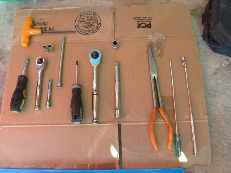
Tools needed:
Other than your normal assortment of smaller metric sockets and the hex drivers there are a couple of specific tools needed. Along with sockets and the few tools listed below I also recommend you invest the $'s and buy a factory shop manual.
• Torque wrench that reads accurately down to 12 Newton /Meters
• Loooooong Phillips screwdriver, 10" or so, #2 head works well, My 8" one barely reached. I needed one more inch; I know, my wife has been tell'n me that for years….
• Cam Chain tensioner release tool. How cool is this, it comes with the new cam chain tensioners. Save this tool for it is the same one you need to make if you do your own valve adjustments.
![237355790-S.jpg]()
• Good flash light; and if you are working alone, don't laugh, but a camping head lamp is invaluable during the work underneath the throttle bodies.
• A bike lift sure helps. If your cheap like me consider the fact that the money you save on labor doing this job will not only pay for a Harbor Freight lift, you will have some $ left over
![237350604-S.jpg]()
Wrenching aids:
Good music always helps, hard to beat these guys,
![238547867-S.jpg]()
This goes well with a bike and a garage. Please note; the amount of use of this wrenching aid can be inversely proportional to quality workmanship.
![238547886-S.jpg]()
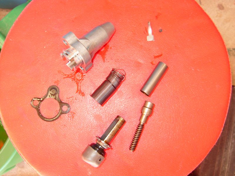
Parts needed:
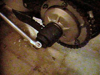
The tensioner is the big ticket item, about $100 each, you need two. There are a couple of other assorted pieces that Honda recommends replacing at the same time; you can decide if you want to replace them. I just replaced them all, I was in there anyway and they were relatively cheap.
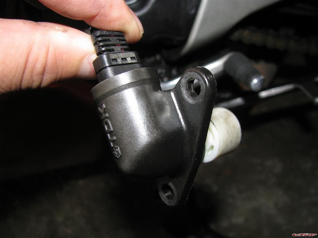
2 Tensioners
![237352111-S.jpg]()
2 Gaskets
![237351575-S.jpg]()
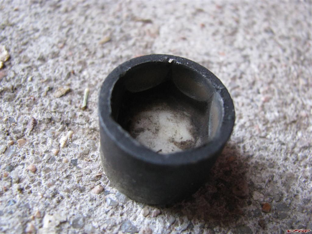
2 Tensioner Washers
![237351807-S.jpg]()
2 Tensioner bolts
![237351700-S.jpg]()
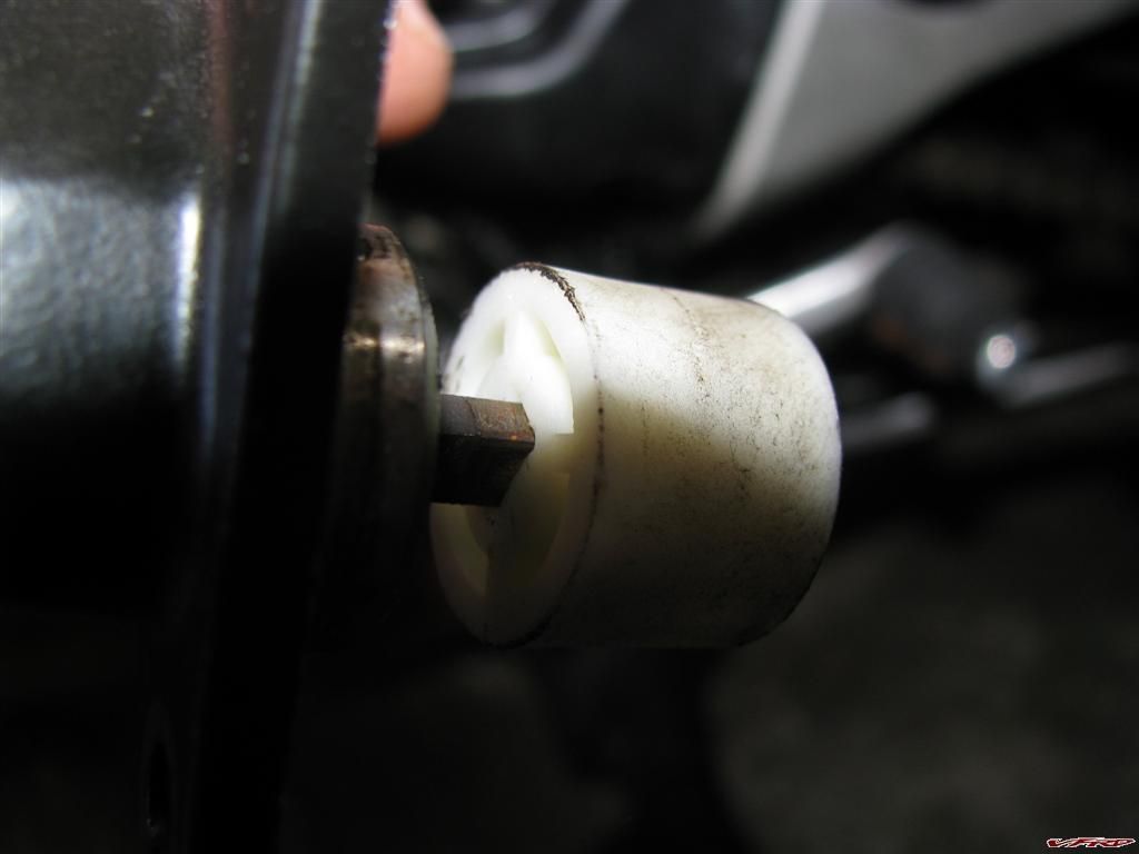
2 Tensioner Buckets, (real name?)
![237351953-S.jpg]()
Tips before you start:
I never trust my memory! I have found it very easy to forget where a bolt or washer goes or where a cable or wire is routed, just a few hours later when it is reassembly time. Solution, for me I do one or more of the following on disassembly.
1. I use my digital camera and photograph every step, especially electrical wires and hose routing for quick reference upon reassembly.
2. I zip-loc bag and mark loose parts
3. I have a hard bound note book I keep detailed notes and sometimes drawings in, if needed.
4. I apply painters tape to each connection I take apart with matching numbers written on them.
5. My favorite; I just thread the screw, bolt or nut right back where I just remove it from. That way it can't get lost and it is right in place for when I reassemble the fitting.
Step 1
Lets start easy; the rear tensioner:
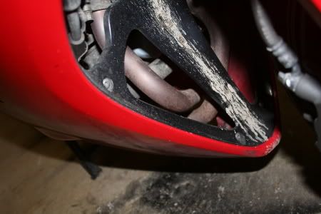
Remove the black metal semicircular heat shield located just behind the drivers right foot peg mount. It is held on by three bolts. Remove the top heat shield bolt first.
![237352572-S.jpg]()
The manual does not state this, but I had to remove the right driver's peg assembly, two large hex bolts, to get the other two heat shield bolts off.
![237353888-S.jpg]()
This is because the lower two bolts, that hold the heat shield in place, have loose nuts and washers located behind the shield. Here I'm reaching behind the shield with a 10mm box end wrench to remove them.
![237354176-S.jpg]()
Once you have the three bolts for the heat shield removed it pulls out with a gentle tug for the top of the shield bends over the top of the exhaust pipe.
Zip tie the foot peg assembly out of the way
![237354299-S.jpg]()
Look, there is the rear tensioner
![237354479-S.jpg]()
Remove the sealing bolt and sealing washer.
![237354639-S.jpg]()
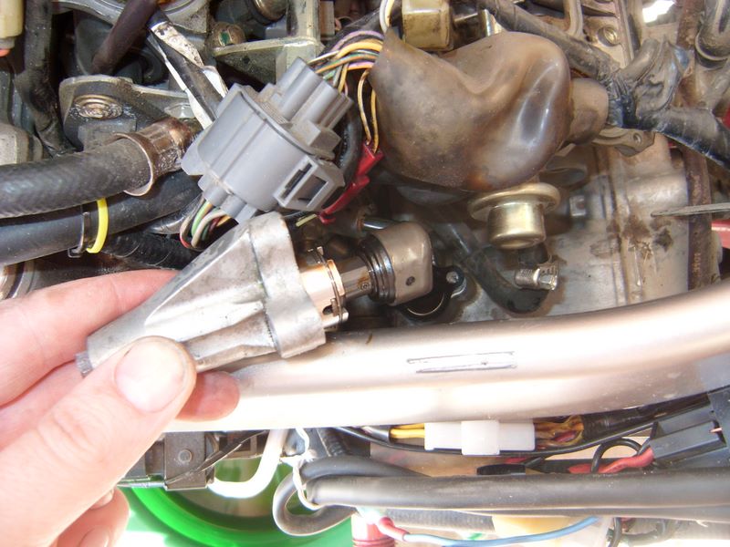
Remove the cam chain stopper tool from the new cam chain tensioner. Hold the rubber ended shaft with one hand so that when you pull the tool straight out it does not allow the shaft too spring out rapidly. If you have not figured out yet what the tool does, here it is; it retracts the spring loaded shaft on the tensioner, and locks it into place during removal and installation. The tool is inserted part way, rotated clockwise until it stops turning then the shoulder section is inserted the rest of the way after you line it up with one of the slots.
Insert the tool, rotate it until it stops and lock it into place in the still installed tensioner; I just used one of the tools I made when I did my valve adjustment.
![237354955-S.jpg]()
Remove the two mounting bolts. It may be just me but I prefer to ease off each bolt a little bit at a time going back and forth between them when ever I remove cast type fittings.
![237355101-S.jpg]()
Pull the tensioner out, pay close attention to the gasket and how the dimple on the "ear" is oriented, mine was with the bumped out part facing the cylinder.
![237355239-S.jpg]()
Install the tool back into the new tensioner. Place the metal bucket (new or old one) on the end of the tensioner; put a new gasket on, just like the old one was. Insert the tensioner into place and tighten the mounting bolts. Nowhere in the manual does it specifically state the cam chain tensioner mounting bolts torque specs. There are two sections that make reference to cam chain tensioner flange bolts and guide bolts, these are both bolts located inside the engine, not the ones we are dealing with. I felt very comfortable using the standard 12nm noted in the VFR manual as the general spec for 6mm, and 8mm flange bolts. No thread loc is indicated anywhere.
Remove the locking tool and install the sealing bolt and sealing washer. I did not use 12nm here, my gut told me the lack of threads (very short bolt length) that 12nm was too much. It is just a seal, so I snuged it about "that" much. I just trusted my well worn Calibrated Wrist Wrench.
![118004664-S-1.jpg]()
A tip here, when you are working with small fasteners I find it best to use the smallest drivers that will do the job, ¼ " works well here and helps prevent you having to post a thread titled something like, ( Is it hard to Heli-Coil?)
Ya did it! The rear is done and now you can reinstall the shield and foot peg bracket.
Front tensioner:
Ok, this one is not hard but if your kind of new to wrenching it may get a bit scary as you start to eviscerate and disembowel your beast. "The only thing to fear, is fear itself", just like our 32nd Prez said.
Remove the seat, This may be just me, a hold over from wrenching cars and bikes for years, I always remove the negative battery lead and zip tie it out of the way when I'm messing too far into an engine, removing gas tanks, or plugging and unplugging a number of electrical connections.
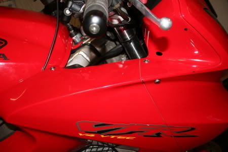
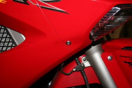
Remove both main fairing side panels; keep track of the 4 different types of fasteners and where they go back.
![237351400-S.jpg]()
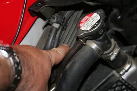
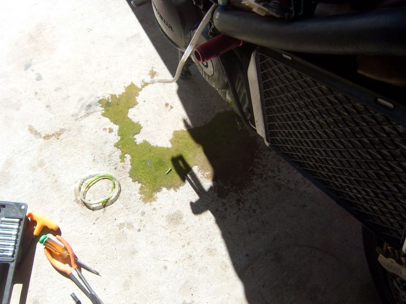
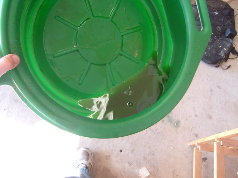
Drain the engine coolant using the drain plug located on lower portion of the water pump on the lower left side of the engine. Remove the radiator cap to do this. I had just changed my coolant a few thousand miles ago, so I saved my coolant in clean containers so I could just reuse it.
![237352721-S.jpg]()
Be ready when you open the radiator cap after the drain plug is out, the coolant leaves the bike much like the proverbial saying "Like a cow piss'n on a flat rock".
![237353127-S.jpg]()
Hopefully you ran your bike down to almost no gas; it just makes handling the gas tank easier. Remove the tank, first the two bolts by the triple clamp. Suggestion, place your hand under the tank bolt holes as you lift the front of the tank and remove both the long shouldered washers now before you hear a slight metallic clank as one falls out into the dark recesses of the frame and engine…Don't ask…..
![237350969-S.jpg]()
Lift the tank, support it, I do it with a motorcycle cargo net hung from above so I can adjust it to any lift level I want. You can also use your tool kit tools as outlined in your owner's manual.
![237356014-S.jpg]()
Remove the upper tank cable fastener.
![237356160-S.jpg]()
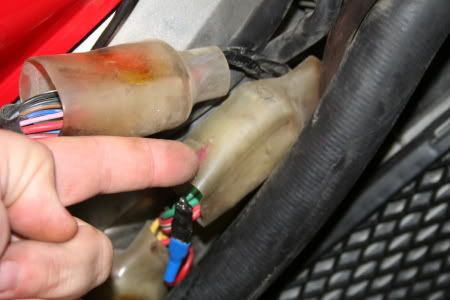
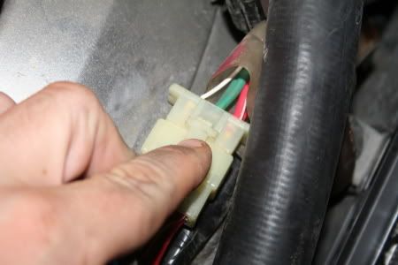
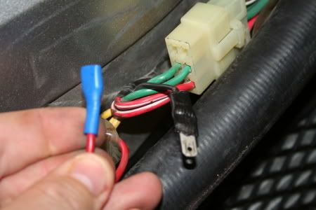
Disconnect the two electrical connections under the tank at the rear by the fuel filter access plate. One is the fuel level sensor, the blue one, and the other is for the fuel pump, the brown one.
![237356298-S.jpg]()
Pop the vent hose and over flow tube out from under the bendable metal keeper connected to the tank.. Rotate the tank 180 degrees and place it on the frame rails after you first place a thick towel down to protect the frame and tank.
![237356762-S.jpg]()
Remove the air cleaner cover screws, un plug the air intake on top of the air cleaner and remove the air box top and the air filter.
Notice the intake stacks, note their positions for reinstall. Folks have messed with these positions, tall rear, short front, tall and short in front and the same in back, etc. So have I; I have never found any noticeable difference. But, I'm sure somewhere someone has increased HP by 20%, boosted gas mileage and cured the Vtec engagement surge just by moving their intakes. Trust your judgment here on reassembly.
![237357077-S.jpg]()
You probably have more plumbing behind the air box than I have, I removed my PAIR Valve hoses, etc a while ago. Disconnect the hoses (if you still have them) to the PAIR Valve solenoid; unplug the map sensor and the vacuum line below it. These are at the rear of the air box.
Stock photo of plumbing back there
![238547851-S.jpg]()
Disconnect the #12 vacuum hose and the grey connector near it. Both are located on the right side of the air box near the front. That is the grey connector and the hose leading away to the lower left from the brown one way valve
![237357489-S.jpg]()
Lift the air box up and disconnect the IAT sensor under the air box.
![237357347-S.jpg]()
Unhook the idle screw adjuster from its keeper, just below the frame rail on the right side. Note: in a few minutes, when you are ready to lift up the throttle bodies, you need to carefully help guide this fitting through the frame openings in order to allow the throttle bodies to be lifted.
![237357870-S.jpg]()
Remove the two shouldered mounting bolts to the coolant over flow tank and zip tie the tank out of the way.
![237358473-S.jpg]()
Hey! Look what I found behind the coolant tank. I lost that tip to my WD-40 about 10,000 miles ago when cleaning the top of the air box.
![237358599-S.jpg]()
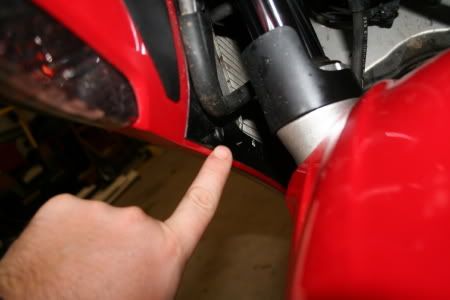
OK, now take a flash light and look around and find the insulators (the rubber tubes that connect the throttle body to the engine) and the hose clamps under each throttle body. I guess you can remove either the insulators with the throttle bodies by loosening the lower hose clamp on each, or have the insulators stay on the engine by loosening each upper hose clamp the way I did. I found it easier to reach the upper hose clamps, thereby leaving the insulators on the engine.
Here is where the loooooong screwdriver fits in. Ya, like the wife said, just two more inches and it would have been even better.
![237358963-S.jpg]()
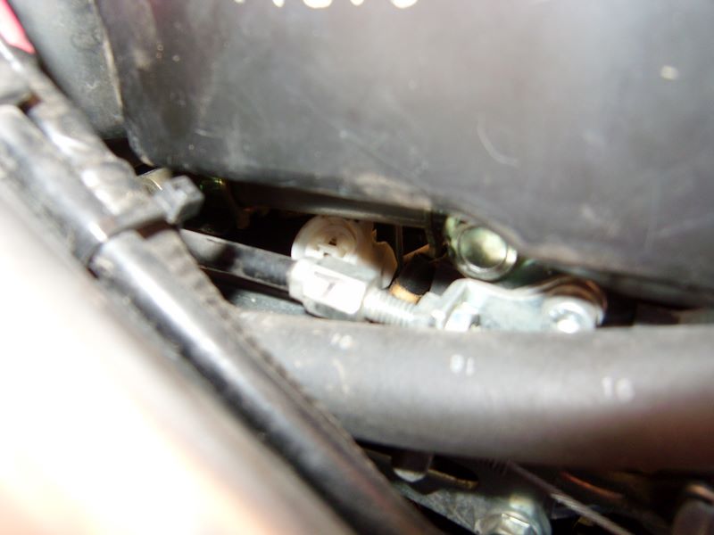
Remove the throttle linkage bolts and the throttle cables.
![237359193-S.jpg]()
Lift off the throttle bodies. Ok, that is not as easy as it sounds, don't lift by the fuel rails. I actually used my favorite hardwood pry thingy to pop the throttle body out of the rubber tube at the rear, then the fronts came out pretty easy.
![237359321-S.jpg]()
Now you must get the two hose clamps off the wax fast idle unit under the throttle bodies. When you look under the throttle bodies it is easy to see that upon assembly of the throttle bodies to the engine this was all done in a different sequence at the factory, confirmed by the fact that you will find hose clamps facing down into the engine.
![237359519-S.jpg]()
Now, I hung the throttle bodies over the bike, ya, that cargo net again and I covered the intake manifold openings with clean rags.
![237360318-S.jpg]()
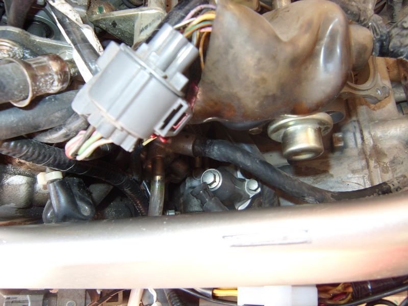
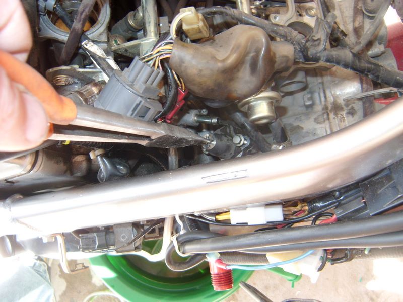
Take a look, there is the Cam Chain Tensioner, whoppie!
![237360153-S.jpg]()
Use the exact same procedure to remove it as you did with the rear one just a bit ago, ya did do the rear one right?
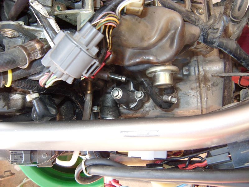
Reassemble in the reverse order. You can use a touch of oil or WD-40 on the insulators lips to help ease the throttle body reassembly. The throttle body intake tubes hose clamps are speced to how tight they should be by noting how close the sides of the clamp are, see pic
![237358795-S.jpg]()
I removed the top hose clamps, they are speced at 7mm. If you removed the bottom ones they are speced at 10mm.
So how do you ever measure that? I just marked it on my screw driver and moved it into position to measure the gaps.
![237358732-S.jpg]()
Sometimes I had to take another long screwdriver and move things out of the way from above to get a clear view. Remember the suggestion about wearing a camping headlamp. Oooooo, it makes easy work of this process; a screw driver in each hand and a light on forehead. Ok, granted ya look stupid wearing it in the garage, but it works.
Ok, now just resemble the beast.


 >
>


